
Related Manuals for intensity ICHS-600KC-5


Summary of Contents for intensity ICHS-600KC-5
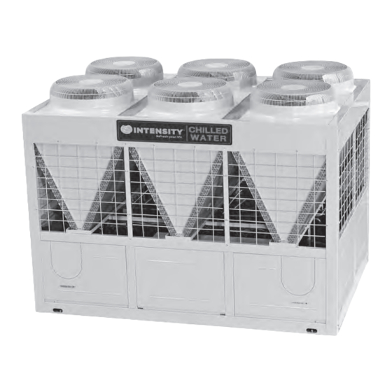
- Page 1 AIR COOLED MODULAR CHILLER ICHS-600KC-5 - 50 TONS. INSTALLATION & OWNER´S MANUAL MAN-I-IOCH50-0715 intensity.mx...
- Page 2 MAIN PARTS OF THE UNIT Air outlet Air outlet Air inlet Air inlet Air inlet Air inlet NAME Top cover Compressor Evaporator Water outlet NAME Electric control box Water inlet Condenser...
- Page 3 OPERATION & PERFORMANCE Performance characteristics of the unit The air-cooled heat pump modular unit is composed of one or more modules. Each module has its own independent electric control unit, and the electric control units of modules conduct information exchange through communication network. The air-cooled heat pump modular unit is characteristics of compact structure and easy transportation and lifting, and in the meanwhile, it also saves facilities, including cooling tower, cooling pump, and so on, for the user, and reduces installation cost.
-
Page 4: Table Of Contents
Never inspect or service the unit by yourself. CONTENTS PAGE Ask a qualified service person to perform this work. PRECAUTIONS................1 Do not dispose this product as unsorted municipal TRANSPORTATION..................2 waste.Collection of such waste separately for special treatment is necessary. INSTALLATION OF THE UNIT..............3 WATER SYSTEM INSTALLATION ...............5... -
Page 5: Transportation
Endurable temperature during transportation is -25 ~55 . After a long use, check the unit stand and fitting for Such equipment could endure 70 of the maximum damage. temperature in 24hrs. If damaged, the unit may fall and result in injury. Do not allow a child to mount on the outdoor unit or avoid To avoid oxygen deficiency, ventilate the room sufficiently placing any object on it. -
Page 6: Installation Of The Unit
Table 3-1 damper. 3.1.8 Consult the building contractor, the architectural Model ICHS-600KC-5 designer or other specialists about the cases with special installation requirements. 2850 NOTE 2000... - Page 7 3.3 Requirements of arrangement space of the unit 3.4 Space requirements for parallel installation of multiple modular units 3.3.1 Requirements of arrangement space of the unit To avoid back flow of the air in the condenser and operational 3.3.1.1 To ensure adequate airflow entering the faults of the unit, the parallel installation of multiple modular condenser, the influence of descending airflow caused by units can follow the direction A and D as shown in Fig.
-
Page 8: Water System Installation
3.6 Installation of damping devices CAUTION 3.6.1 Damping devices must be provided between the unit ● After the unit is in place, chilled water pipes can be laid. and its foundation. ● The relevant installation regulations should be abided with By means of the Φ15mm diameter installation holes on the when conducting connection of water pipes. - Page 9 m. The outdoor chilled water pipelines should be wrapped o. The common outlet pipelines of combined units should with an auxiliary heating belt for heat preservation, and the be provided with mixing water temperature sensor. material of the auxiliary heat belt should be PE, EDPM, etc., with thickness of 20mm, to prevent the pipelines from freezing and thus cracking under low temperature.
- Page 10 For maximum chilled water flow rate Evaporator Error Recirculation Fig. 4-3 4.5 Minimum and Maximum water flow rates Recommendation Error Table 4-1 Fig.4-4 Water flow rate(m Item Maximum Minimum Model 27.9 34.1 ICHS-600KC-5 O&I manual...
- Page 11 4.7 Selection and installation of the pump 4.8.2 Applicable standard of water quality for the unit 4.7.1 Select the pump Table 4-2 a. Select the water-flow of the pump 7 8.5 PH value The rated water-flow must no less than the unit rated water-flow; in terms of multi-connect the units, that water-flow must no less Total hardness <50ppm...
- Page 12 d. Special grounding screws should be used for earth f. Be sure to determine the model of target slice according to the connection. Bolts should not be installed or removed at will; rated flow of the unit, the diameter of the outlet pipe and the otherwise flow switches may suffer deformation and failure.
- Page 13 4.11 Installation of multi-module water system pipe- line Multi-module combination installation involves special design of the unit, so relevant explanation is given as follows. 4.11.1 Installation mode of multi-module combination water system pipeline a. Installation mode I (recommended installation mode) No.1 unit No.(n-1) unit No.n unit (n≤5)
- Page 14 4.11.2 Table of diameter parameters of main inlet and outlet pipes Table 4-3 CAUTION Please pay attention to the following items when installing multiple modules: O&I manual...
-
Page 15: Electric Wiring
5. ELECTRIC WIRING 5.3.6 All power supplies connected to the unit must pass one manual switch, to ensure that the voltages on all nodes of electric circuit of the unit are released when the switch is cut off. 5.1 Electric wiring 5.3.7 The cables of correct specification must be used to supply power for the unit. - Page 16 Step 5. The wires of the main power must pass the bonding clamp. Step 6. Wires should be connected firmly to the connection terminals A, B, C and N. Step 7. Phase sequences must be consistent when the wires of the main power. Step 8.
- Page 17 5.6 Detail description for parts in fig. 5-4 Table 5-2 Detail information Detection of current of the compressor B (protection code P5) Detection of current of the compressor A (protection code P4) Current is not detected within the initial 5 seconds after the compressor is started up. When the current of the compressor is detected to exceed protective value set (33A for constant speed compressor), it will be shut down and re-started after 3 min.
- Page 18 Detail information Each modular part of modular unit has the same electric control function, and the main unit and When the subordinate units can be set through address code address is 0, it on the electric control board. The address code 0 # serves as the is provided as the main unit.
- Page 19 Detail information Auxiliary electric heater Attention: the control port value of auxiliary electric heater actually detected is ON/OFF but not 220-230V control power supply, so special attention should be paid when installing the auxiliary electric heater. Attention! Under heating mode, when the main unit board detects total water outlet temperature to be lower than 45 , the switch will be closed, and the auxiliary electric heater will begin to work;...
-
Page 20: Trial Run
6. TRIAL RUN 6.1 Points for attention prior to trial run 6.1.1 After the water system pipeline is flushed several times, please make sure that the purity of water meets the requirements; the system is re-filled with water and drained, and the pump is started up, then make sure that water flow and the pressure at the outlet meet the requirements. -
Page 21: Use
6.3 Trial run 6.3.1 Start up the controller and check whether the unit displays a ● The target flow controller must be installed correctly. The fault code. If a fault occurs, remove the fault first, and start the wires of the target flow controller must be connected according unit according to the operating method in the “unit control to electric control schematic diagram, or the faults caused by instruction”, after determining that there is no fault existing in the... - Page 22 7.2 Operating instructions of buttons 10 Address decrease Press the button under Spot check display state to select the 1 Startup/shutdown button previous modular unit to display its operation state data. If it Under power-off state, press the button, the startup indicator lamp comes to 0# modular unit, select 15# unit after pressing the is turned on, and the wired controller enters power-on state, and in button.
- Page 23 7.3 ON/OFF Follow the following diagram for system ON/OFF Turn on the unit Power up to module unit and initially deliver power to wire control. Press the key again until all Press “mode settings” key to set the modes are showed (i.e. Cooling, intended mode.
- Page 24 7.4 Control and protection function of unit 5) Protection for compressor overload 6) Anti-freezing protection 7) Protection for over-high discharge pressure 8.1.1 The unit has the following protection functions 8) Protection for outlet and inlet water temperature 1) Current cut-off protection difference 8.1.2 The unit also has other control functions: 2) Power supply phase sequence protection 1) Manual test function...
-
Page 25: Maintenance And Upkeep
Table 7-1 Error Possible reason Detect and settle measure Over high air expelling pressure and See “Over high air expelling pressure” and “Over high air suction pressure” air suction pressure Compressor stops Hi-voltage or Lo-voltage, signal phase Confirm voltage not higher or lower than the rated voltage 20V because of motor or phase unbalance Overcurrent. - Page 26 8.1.2 Failure information and code 8.1.3 Ordinary displayed data In case the unit runs under abnormal condition, failure a. Ordinary displayed data are displayed in all display pages. protection code will display on both control panel and wired controller, and the indicator on the wired controller will flash b.
- Page 27 8.1.7 Care and maintenance g. Display of online unit number and startup unit number They are used for displaying the total online modular units of the whole unit system and the number of the modular unit under Maintenance of main parts running state, respectively, with display scope 0~16.
- Page 28 1) If the unit that is shutdown for standby is placed in an 8.1.12 Refrigeration system environment where the outdoor temperature is lower than 2 , the water in the water system should be drained. Determine whether refrigerant is needed by checking the value 2) Water pipe may be frozen when the chilled water target of suction and discharge pressure and check whether there is a flow controller and anti-freezing temperature senor become...
- Page 29 RECORD TABLE OF TEST RUN AND MAINTENANCE Table 8-2 Model: Code labeled on the unit: Customer name and address: Date: 1. Whether there is sufficient water flow passing waterside heat exchanger? ( 2. Whether leakage detection has been made on all the water pipe? 3.
- Page 30 RECORD TABLE OF ROUTINE RUNNING Table 8-3 Model: Date: Weather: Operation time: Startup ( Shutdown ( Dry bulb Outdoor temperature Wet bulb Indoor temperature High pressure Low pressure Compressor Voltage Current Inlet (dry bulb) Air temperature of air-side heat exchanger Outlet (dry bulb) Inlet...
-
Page 31: Applicable Models And Main Parameters
9. APPLICABLE MODELS AND MAIN PARAMETERS Table 9-1 Model ICHS-600KC-5 Cooling capacity Heating capacity Cooling consuming power 58.5 Cooling rated current 189.0 Heating consuming power 60.0 Heating rated current 196.5 Power supply 220V 3N 60Hz Control of wired controller, manual/auto startup, running state Operation control display, failure alert etc. -
Page 32: Attached Drawing (I)
KM12 KM11 KM10 O&I manual... -
Page 33: Attached Drawing (Ii)
O&I manual...
Need help?
Do you have a question about the ICHS-600KC-5 and is the answer not in the manual?
Questions and answers