
Related Manuals for intensity ICHS-120KC-5


Summary of Contents for intensity ICHS-120KC-5
- Page 1 AIR COOLED MODULAR CHILLER ICHS-120KC-5 - 10 TONS. INSTALLATION & OWNER´S MANUAL intensity.mx MAN-I-IOCH10-0715...
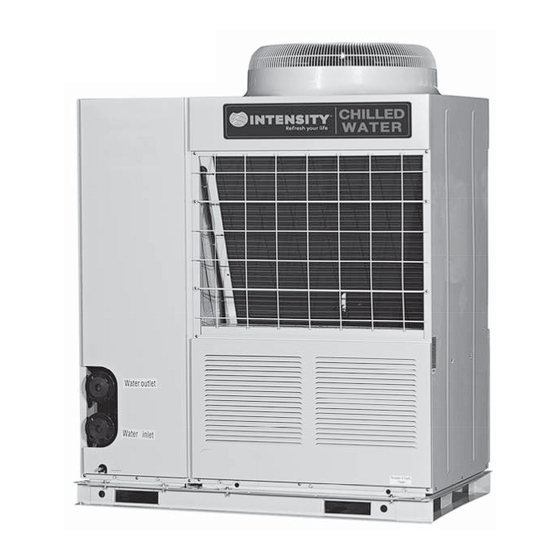
- Page 2 MAIN PARTS OF THE UNIT MAIN PARTS OF THE UNIT Electric Electric NAME NAME Top cover Top cover Air outlet Air outlet Air outlet Air inlet Air inlet Water outlet Water outlet Water inlet Water inlet control box control box...
- Page 3 OPERATION & PERFORMANCE OPERATION & PERFORMANCE Performance characteristics of the unit Performance characteristics of the unit The air-cooled heat pump modular unit is composed of one or more modules. Each module has its own independent electric The air-cooled heat pump modular unit is composed of one or more modules. Each module has its own independent electric control unit, and the electric control units of modules conduct information exchange through communication network.
-
Page 4: Table Of Contents
Never inspect or service the unit by yourself. Never inspect or service the unit by yourself. CONTENTS CONTENTS PAGE PAGE Ask a qualified service person to perform this work. Ask a qualified service person to perform this work. Do not dispose this product as unsorted municipal Do not dispose this product as unsorted municipal PRECAUTIONS................1 PRECAUTIONS................1... -
Page 5: Transportation
Endurable temperature during transportation is -25°C~55°C. Endurable temperature during transportation is -25°C~55°C. After a long use, check the unit stand and fitting for damage. After a long use, check the unit stand and fitting for damage. Such equipment could endure 70°C of the maximum Such equipment could endure 70°C of the maximum If damaged, the unit may fall and result in injury. -
Page 6: Installation Of The Unit
3. INSTALLATION OF THE UNIT 3. INSTALLATION OF THE UNIT... - Page 7 3.3 Requirements of arrangement space of the unit 3.3 Requirements of arrangement space of the unit 3.4 Space requirements for parallel installation of 3.4 Space requirements for parallel installation of multiple modular units multiple modular units 3.3.1 Requirements of arrangement space of the unit 3.3.1 Requirements of arrangement space of the unit To avoid back flow of the air in the condenser and operational To avoid back flow of the air in the condenser and operational...
-
Page 8: Water System Installation
WATER SYSTEM INSTALLATION WATER SYSTEM INSTALLATION 3.6 Installation of damping devices 3.6 Installation of damping devices 3.6.1 Damping devices must be provided between the unit 3.6.1 Damping devices must be provided between the unit 4.1 Basic requirements of connection of chilled 4.1 Basic requirements of connection of chilled and its foundation. - Page 9 l. All possible water pipes in the system to be chilled should be l. All possible water pipes in the system to be chilled should be o. The common outlet pipelines of combined units should be o. The common outlet pipelines of combined units should be under heat preservation, including inlet pipes and flanges of the under heat preservation, including inlet pipes and flanges of the provided with mixing water temperature sensor.
- Page 11 4.7 Selection and installation of the pump 4.7 Selection and installation of the pump 4.9 Installation & regulation guide for target flow 4.9 Installation & regulation guide for target flow controller controller 4.7.1 Select the pump 4.7.1 Select the pump 4.9.1 4.9.1 Please carefully check flow switches before conducting...
- Page 12 Be sure to determine the model of target slice according to Be sure to determine the model of target slice according to 4.10 Installation of single-module water system 4.10 Installation of single-module water system the rated flow of the unit, the diameter of the outlet pipe the rated flow of the unit, the diameter of the outlet pipe pipeline pipeline...
- Page 13 10 10...
-
Page 14: Electric Wiring
5. ELECTRIC WIRING 5. ELECTRIC WIRING... - Page 15 Step 7. Phase sequences must be consistent when the wires of the main power. Step 7. Phase sequences must be consistent when the wires of the main power. Step 8. The main power should be located out of easy reach of non-professional maintenance personnel, to avoid mal-operation and Step 8.
- Page 16 5.6 Detail description for parts in fig. 5-5 5.6 Detail description for parts in fig. 5-5 Table 5-2 Table 5-2 Detail information Detail information Detection of current of the compressor B (protection code P5) Detection of current of the compressor B (protection code P5) Detection of current of the compressor A (protection code P4) Detection of current of the compressor A (protection code P4) Current is not detected within the initial 5 seconds after the compressor is started up.
- Page 17 Detail information Detail information Each modular part of modular unit has the same Each modular part of modular unit has the same electric control function, and the main unit and electric control function, and the main unit and When the When the subordinate units can be set through address code subordinate units can be set through address code...
- Page 18 Detail information Detail information Auxiliary electric heater Auxiliary electric heater Attention: the control port value of auxiliary electric heater actually detected is ON/OFF but not 220-240V control Attention: the control port value of auxiliary electric heater actually detected is ON/OFF but not 220-240V control power supply, so special attention should be paid when installing the auxiliary electric heater.
-
Page 19: Trial Run
6. TRIAL RUN 6. TRIAL RUN 6.1 Points for attention prior to trial run 6.1 Points for attention prior to trial run 6.1.1 6.1.1 After the water system pipeline is flushed several times, please make sure that the purity of water meets the requirements; the After the water system pipeline is flushed several times, please make sure that the purity of water meets the requirements;... -
Page 20: Use
6.3 Trial run 6.3 Trial run ● The target flow controller must be installed correctly. The ● The target flow controller must be installed correctly. The wires of the target flow controller must be connected according wires of the target flow controller must be connected according 6.3.1 Start up the controller and check whether the unit displays a 6.3.1 Start up the controller and check whether the unit displays a to electric control schematic diagram, or the faults caused by... - Page 21 7.2 Operating instructions of buttons 7.2 Operating instructions of buttons Address decrease Address decrease Press the button under Spot check display state to select the Press the button under Spot check display state to select the Startup/shutdown button Startup/shutdown button previous modular unit to display its operation state data.
- Page 22 7.3 ON/OFF 7.3 ON/OFF Follow the following diagram for system ON/OFF Follow the following diagram for system ON/OFF Turn on the unit Turn on the unit Power up to module unit and initially deliver Power up to module unit and initially deliver power to wire control.
- Page 23 7.4 Control and protection function of unit 7.4 Control and protection function of unit 5) Protection for compressor overload 5) Protection for compressor overload 6) Anti-freezing protection 6) Anti-freezing protection 7) Protection for over-high discharge pressure 7) Protection for over-high discharge pressure The unit has the following protection functions The unit has the following protection functions 1) Current cut-off protection...
-
Page 24: Maintenance And Upkeep
Table 7-1 Table 7-1 Error Error Possible reason Possible reason Detect and settle measure Detect and settle measure Over high air expelling pressure and Over high air expelling pressure and See “Over high air expelling pressure” and “Over high air suction pressure” See “Over high air expelling pressure”... - Page 25 8.1.3 Ordinary displayed data 8.1.3 Ordinary displayed data 8.1.2 Failure information and code 8.1.2 Failure information and code In case the unit runs under abnormal condition, failure protection In case the unit runs under abnormal condition, failure protection a. Ordinary displayed data are displayed in all display pages. a.
- Page 26 Any time when the spot check page is entered to display or Any time when the spot check page is entered to display or 8.1.7 Care and maintenance 8.1.7 Care and maintenance change modular unit, it is needed to wait for the up-to-date data change modular unit, it is needed to wait for the up-to-date data of the modular unit received and selected by wired controller.
- Page 27 8.1.12 Refrigeration system 8.1.12 Refrigeration system 8.1.13 Disassembling compressor 8.1.13 Disassembling compressor Determine whether refrigerant is needed by checking the value Determine whether refrigerant is needed by checking the value Follow the following procedures if compressor needs to be Follow the following procedures if compressor needs to be of suction and discharge pressure and check whether there is a of suction and discharge pressure and check whether there is a disassembled:...
- Page 28 RECORD TABLE OF TEST RUN AND MAINTENANCE RECORD TABLE OF TEST RUN AND MAINTENANCE Table 8-2 Table 8-2 Model: Model: Code labeled on the unit: Code labeled on the unit: Customer name and address: Customer name and address: Date: Date: 1.
- Page 29 RECORD TABLE OF ROUTINE RUNNING RECORD TABLE OF ROUTINE RUNNING Table 8-3 Table 8-3 Model: Model: Date: Date: Weather: Weather: Operation time: Startup ( Operation time: Startup ( Shutdown ( Shutdown ( Dry bulb Dry bulb Outdoor Outdoor temperature temperature Wet bulb Wet bulb Indoor temperature...
-
Page 30: Applicable Models And Main Parameters
9. APPLICABLE MODELS AND MAIN PARAMETERS 9. APPLICABLE MODELS AND MAIN PARAMETERS... -
Page 31: Attached Drawing (I)
installation & owner’s manual installation & owner’s manual... -
Page 32: Attached Drawing (Ii)
installation & owner’s manual installation & owner’s manual...
Need help?
Do you have a question about the ICHS-120KC-5 and is the answer not in the manual?
Questions and answers