Table of Contents
Advertisement
Quick Links
NAPCO Net.Link
NL-RCV-RMPCUL
™
R
Central Station Alarm Receiver
333 Bayview Avenue
Amityville, New York 11701
Installation, Programming and User's Guide
For Sales and Repairs, (800) 645-9445
For Technical Service, (800) 645-9440
Publicly traded on NASDAQ
Symbol: NSSC
http://www.napcosecurity.com/
WI1491A 5/07
© NAPCO 2007
Installing, Programming and Using the
NAPCO Net.Link NL-RCV-RMPCUL
TM
Central Station Alarm Receiver
1
Advertisement
Table of Contents

Subscribe to Our Youtube Channel
Related Manuals for NAPCO Net.Link NL-RCV-RMPCUL

Summary of Contents for NAPCO Net.Link NL-RCV-RMPCUL
- Page 1 Installation, Programming and User's Guide For Sales and Repairs, (800) 645-9445 For Technical Service, (800) 645-9440 Publicly traded on NASDAQ Symbol: NSSC http://www.napcosecurity.com/ WI1491A 5/07 © NAPCO 2007 Installing, Programming and Using the NAPCO Net.Link NL-RCV-RMPCUL Central Station Alarm Receiver...
-
Page 2: Table Of Contents
Appendix B ..........................26 NAPCO LIMITED WARRANTY ....................28 NAPCO Net.Link is a registered trademark of the NAPCO Security Group, Inc. Windows is a registered trademark of the Microsoft Corporation. Other products, product names and services described in this manual are for identification purposes only and may be trademarks of their respective companies. -
Page 3: Fcc Requirements
FCC Requirements The NL-RCV-RMPCUL Receiver complies with part 15 of the FCC rules. THE FOLLOWING STATEMENT IS REQUIRED BY THE FCC. This equipment generates and uses radio-frequency energy and, if not installed and used properly, that is, in strict accordance with the manufacturer's instructions, may cause interference to radio and television reception. -
Page 4: Napco Net.link™ Receiver System Overview
Operator 3 Operator ... Since early 2004, the NAPCO Net.Link TCP/IP alarm reporting system has proven its reliability in the field. The Net.Link system was designed to conform to all UL requirements for Packet Switched Data Networks, and consequently the NAPCO Net.Link™... -
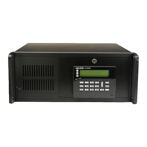
Page 5: Front Housing Description
Front Housing Description Open here FRONT PANEL--CLOSED Reset Red LED Green LED Keyboard Lock Power FRONT PANEL--OPEN FRONT PANEL--DETAIL FRONT PANEL See images above. The front panel includes a dedicated keypad with an LCD display, and a locking faceplate located behind the mounted keypad. -
Page 6: Rear Housing Description
110VAC three-pronged input jack (supplied). NAPCO part #W943). Required only for Hot Backup (Current draw = 1.2A max). failover configuration (see page 7). • Main Power Switch - Switch for main Receiver power supply. Note: This switch only supplies AC Relay Card: power and does not cause the software to run. -
Page 7: Installation And Startup
Receivers. The transmitters are defaulted to send over cable (e.g., NAPCO part #W943) to the LAN2 socket of events to Port 5001, and the Receiver listening port must one Receiver, and connect the other end of the same cross- match this port number, otherwise see page 23 to change the over cable to the LAN2 socket of the other Receiver. - Page 8 Re- ceiver will be configured as a Hot Backup Receiver. Con- nect both ends of the RJ-45 crossover cable (e.g. NAPCO part #W943) to the LAN2 socket of both Receivers if you want both Receivers to act together--one as an Active Re- ceiver and the other as a Hot Backup Receiver.
- Page 9 Active Net.Link Receiver. The list of Re- SERVICE TERMINAL SOFTWARE INSTALLATION Connected to the router, the NAPCO Net.Link Service Termi- ceivers will automatically populate. Click the Find Receivers nal is a PC that runs the Net.Link Service Application soft- button to refresh the Receiver list.
- Page 10 Installation and Startup (cont'd) Automation Setup This section covers the options for sending events to the Automation Host computer system. Click Tools, Automation Setup and the following Auto- mation Setup dialog appears: The New Account Setup dialog allows you to configure Ac- count information.
- Page 11 Installation and Startup (cont'd) Heart-Beat Interval in seconds Click this pull-down list to select the number of seconds be- tween a "Heart Beat" signal being sent to the Automation Host computer. Receiver Section The Receiver section of this dialog is used to configure the Receiver Number and Line Card Number required by some automation systems.
-
Page 12: Keypad: Operation And Display
Keypad: Operation and Display net.link by NAPCO Napco Net.Link Automatic Mode SYS TBL MENU STATUS PREV CLEAR provides a Yes/No LCD Display - Consists of STATUS Button - two rows of 16 characters Reserved for future use. response to Menu View each and a SYS TBL icon. -
Page 13: Keypad: Automatic Mode
Keypad: Automatic Mode The system operation includes two modes: Automatic Mode and Manual Mode. AUTOMATIC MODE N a p c o N e t . L i n k A u t o m a t i c M o d e When an Automation Host is used, the display will auto- matically indicate Automatic Mode. -
Page 14: Keypad: Manual Mode
Keypad: Manual Mode Manual Mode Burglary, 110 = Fire, etc.); the next two digits identify the area number, and the final three digits identify the Zone or User number. N a p c o N e t . L i n k M a n u a l M o d e Idle Keypad Display in Manual Mode Acknowledging Events / Troubles... -
Page 15: Keypad: Menu View
Keypad: Menu View SYSTEM TESTS View System Tbls The following system tests can be performed at the key- pad. System Tests... KeyPad Test Keypad Test Printer Test The Keypad test will prompt the operator through a se- System Info... ries of tasks to ensure that the keypad is fully functional. Net.Link Version If the test fails, a system trouble will be generated. - Page 16 Keypad: Menu View (cont'd) CONFIGURATION Change Virtual IP Address Allows the last 3 digits of the Virtual IP Address to be changed at the keypad and press the ENT/ACK key. The keypad will read "Virt IP Updated". Note: The Vir- tual IP address can be manually assigned at the keypad at any time.
-
Page 17: Printout Of Events
Printout of Events The printout of the Receiver is easily interpreted. Typical signals are printed as follows on an 80-column printer: 01/04/2006 02:17:27 PM 01 0036 E602 06 U/Z 194 Fail to Check-In - Date MM/DD/YYYY 01/04/2006 - Time HH:MM:SS AM or PM 02:17:27 PM - Ordinal number sequencing the events for each Subscriber ID - Subscriber ID... -
Page 18: Net.link Service Application Quick Access Buttons
Net.Link Service Application Quick Access Buttons The Net.Link Service Application toolbar (above) contains the Quick Access buttons. It may be helpful to open each screen on your computer as you read. From left to right, they are as follows: Log Off - Logs the current operator off the Locate Active Receivers - Click this button to system. -
Page 19: Using The Service Application
Using the Service Application The NAPCO Net.Link Service Application is a PC-based See page 18 for a full listing of all button names and menu software program that is designed to maintain accounts and names in this main screen. provide a means of displaying status changes and event his- tory. - Page 20 Using the Service Application (cont'd) File, Select Account>>View Panel Status Click File, Select Account, View Panel Status and the Select Account window opens: Click to highlight an Account and click OK. The Panel Status dialog appears (shown below) and the selected Account now becomes the active Account: File, Edit Active Account Click File, Edit Active Account (or press CTRL+E) and...
- Page 21 Using the Service Application (cont'd) If the Event Queue is closed, it can always be opened by search for Events by Event Type. Type a specific Event Type in the Type in Event Type field. The event Area clicking View, Event Queue, by pressing F5, or by click- ing its Quick Access button (the tooltip "Event Queue of and Zone can also be specified with their respective drop the Currently Selected Receiver"...
- Page 22 Using the Service Application (cont'd) Tools, Manage Users 3. The areas of the Add User screen are as follows: User Name: Type a "user name" to represent a central station operator in the User field. Full Name: Type the full name of the user, identi- fying the actual person.
- Page 23 Using the Service Application (cont'd) Action, Set Password. This option is used to change The Virtual IP Address Entry screen displays the IP the password of an existing user. To set a password address that is shared between the Active and Hot Backup Receivers.
- Page 24 Using the Service Application (cont'd) ceiver be restarted for the new port number settings to take effect: Tools, Set Regional Time for Receiver This option is used to update the regional Time Zone settings for the Receiver's internal realtime clock. In the Select New Time Zone screen (shown above), the top half of this screen displays the current regional settings and the date.
- Page 25 APPENDIX A SYSTEM TROUBLES All system troubles are sent to Automation Host computer when Automation is in use. The Contact ID code that is sent is an E300/R300 of the area and the SubID will always be zero (0) and the zone number will have one of the following numbers to identify the system trouble: 100 = Hot Backup Off Line 102 = LAN Network Failure...
- Page 26 APPENDIX B PROTOCOL INFORMATION FOR THE AUTOMATION HOST COMPUTER The Sur-Gard SG-SLR (Single Line Receiver) Contact ID protocol is used for host communication. Only the "Automatic Mode" selection supports a "Heart Beat" signal being sent to the host computer (every 10 seconds). The "Heart Beat"...
- Page 27 NOTES...
-
Page 28: Napco Limited Warranty
NAPCO will, within said In no event shall NAPCO be liable for an amount in ex- period, at its option, repair or replace any product failing cess of NAPCO's original selling price of the product, for...
Need help?
Do you have a question about the Net.Link NL-RCV-RMPCUL and is the answer not in the manual?
Questions and answers