Advertisement
These instructions are for your safety. Please read through them thoroughly
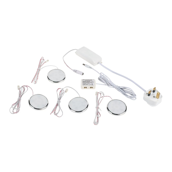
Ref
Description Illustration
A
Head unit,
cable and
connector
B
Loom and junction box
Tools Required (not supplied)
6mm Cross Headed Screwdriver
Pencil
Before You Start
•
Decide on an appropriate location for your product (see siting instructions below).
•
If you are in any doubt about installing this product, consult a qualified electrician.
Siting Instructions
1.
This product is designed for use under kitchen cupboards, bookshelves, cabinets etc.
Suitable for indoor use only. Not suitable for bathrooms.
2.
Do not attach to surfaces which are damp or freshly painted.
3.
The chosen location should allow for the product to be securely mounted and safely
connected to the mains supply (240V wall socket or fused outlet socket).
4.
Ensure cables are routed to avoid accidental damage or hazard.
Installation
1. Lay out/ measure the positions of the head units as desired. Ensure you route cables to avoid
accident or damage occurring. Cables can be taped to mounting surface after installation.
2. Each head unit is supplied with 1m of cable. The cable from the junction box to the
transformer lead and plug 2.5m long. See Fig 1 for example layout.
29.07.11
Installation and Safety Instructions
LAP LED Disk downlights kit 4pk
before use and retain for future reference.
Qty
Ref
Description Illustration
C
Plug, LED Transformer
4
0.5m cable
1
D
Fixings kit
Screw
Adhesive pad
Adhesive
pad cut-out
shapes
White LED: 24907
Blue LED: 55495
Qty
1
8
1
1
Page 1 of 2
Advertisement
Table of Contents

Related Manuals for lap 24907

Summary of Contents for lap 24907
- Page 1 White LED: 24907 Blue LED: 55495 Installation and Safety Instructions LAP LED Disk downlights kit 4pk These instructions are for your safety. Please read through them thoroughly before use and retain for future reference. Ref Description Illustration Ref Description Illustration Head unit, Plug, LED Transformer cable and 0.5m cable connector Loom and junction box Fixings kit Screw Adhesive pad Adhesive pad cut-out shapes Tools Required (not supplied) 6mm Cross Headed Screwdriver Pencil Before You Start • Decide on an appropriate location for your product (see siting instructions below). • If you are in any doubt about installing this product, consult a qualified electrician.
- Page 2 3. Attach heads in position using either the supplied screws or self adhesive pads. If using the screws to fix the heads you will need to separate the head from the frame. Carefully push on the rear of the LED unit, towards the edge. See Fig 1. There is a knock out on one edge so the cable can be laid flat to the surface. Screw the frame to the mounting surface ensuring the cable is passing through the knock out. When the frame is secure, carefully push the LED unit back into position. 4. Fix junction box to mounting surface using supplied adhesive pad. Connect all heads to the junction box, route loom (B) to desired power source (240V mains socket or fused outlet socket - see connection section below). Take care not to create a trip hazard. Cables can be tidied and secured to the mounting surface using tape or small clips (not supplied).
Need help?
Do you have a question about the 24907 and is the answer not in the manual?
Questions and answers