Table of Contents
Advertisement
Quick Links
Advertisement
Table of Contents

Related Manuals for Daking Audio Mic Pre 4T


Summary of Contents for Daking Audio Mic Pre 4T
- Page 1 Daking Audio Daking Audio Mic Pre 4T Manual VERSION 2 10/5/21...
- Page 2 Safety Considerations 1. Read, follow and keep these instructions. 2. Heed all warnings. 3. Do not use this equipment in or near water. Do not place liquids on or near the device because the device might be damaged during a spill. 4.
-
Page 3: Table Of Contents
............... 1.5.7 +48 Button ............... 1.5.8 Ø Button ................1.6 Signal Flow: Patching Into and Out of Your Mic Pre 4T ..1.6.1 Microphone to Mic Pre 4T to Audio Interface or Mixer ..1.6.2 Via a Patch Bay ............... -
Page 4: Daking Audio Mic Pre 4T
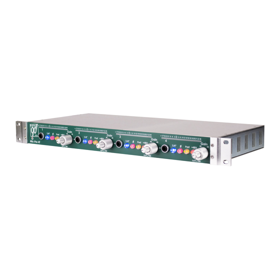
1 Daking Audio Mic Pre IV 1.1 About Daking Audio Congratulations! You’ve purchased a Mic Pre 4T, a very high end piece of gear! The Mic Pre 4T uses all-discrete transistor Class A circuits, Jensen input and output transformers, and printed circuit board mounted switches. -
Page 5: Basic Set Up
Plug a microphone into the Mic Input Jack on one of the four preamps on the Mic Pre 4T using a microphone (XLR Female to XLR Male) cable. If the mic you are using is a condenser microphone that requires phantom power,... -
Page 6: In General: Xlr Connectors And ¼" Trs Connectors
1.4.1 In General: XLR Connectors and ¼” TRS Connectors XLR connectors are more expensive, more reliable and offer a stronger connection than ¼” TRS connectors. They also have the option of a locking latch that helps to keep the cable from being pulled out accidentally. If worst comes to worst, you can connect two XLR cables together to make a longer run. -
Page 7: Microphone Input (Xlr)
1.4.2 Microphone Input (XLR) The microphone input accepts a mic-level signal. Mic level signals are generally very low in voltage: around a couple of millivolts, or thousandths of a volt. The job of the mic preamp is to increase the mic output signal by as much as 75 dB to line level, which is between 1 and 2 volts. -
Page 8: Front Panel
1.5 Front Panel 1.5.1 LED VU and Peak Meter The VU Meter for the Mic Pre 4T is a true VU Meter with 300ms averaging ballistics. The main difference between this meter and a mechanical VU meter is that this meter extends to +25dB, while a mechanical meter only goes up to +3dB. -
Page 9: Gain Knob
VU meter, hearing audible clipping or distortion, or overloading the following stage in the signal chain. For instance, your Mic Pre 4T can support outputs up to +26dB, but most audio interfaces clip at +18dB. The gain control would have to be set so as to not overload the audio interface. -
Page 10: Instrument Input Jack
There are a number of problems with tracking these very low and often unwanted frequencies. Low frequency problems can come from traffic or subway noise hundreds of feet away. A concrete or wood-joisted floor is essentially an enormous drum head and every footstep creates low frequency energy which can easily travel into microphones. -
Page 11: Button
to use the front ¼” jack. 1.5.5 ¼” Button This button switches the input of the mic pre to the front ¼” input and disengages the rear mic input. 1.5.6 Pad Button The Pad button is a 20dB attenuator useful when the gain knob is in its lowest position and the peak indicator (*) is still being lit. -
Page 12: Signal Flow: Patching Into And Out Of Your Mic Pre 4T
1.6 Signal Flow: Patching In and Out of Your Mic Pre 4T 1.6.1 Microphone to Mic Pre 4T to Audio Interface or Mixer Basic Cables Needed: (1) Microphone Type Cable (Female XLR to Male XLR) (1) Female XLR to Male ¼” TRS Balanced Cable Patch from the microphone to the mic input on the MP 4T using the female XLR to male XLR microphone cable. - Page 13 Cables Needed: (2)XLR Male to ¼” TRS Male (3)XLR Female to ¼” TRS Male Steps: 1. Patch from the bottom back jack on the patch bay module to an input on the MP 4T using the ¼” TRS to XLR Male cable. 2.
-
Page 14: Specifications
1.7 Specifications • Transformer balanced inputs and output • Highest quality American-made Jensen Transformers All-discrete transistor circuitry • Class "A" amplifiers • Continuously Variable Gain Control • 20 Segment VU Meter (-20 to +25) • +26dB Peak indicator • All relay switching w/gold bifurcated contacts •...
Need help?
Do you have a question about the Mic Pre 4T and is the answer not in the manual?
Questions and answers