Table of Contents
Advertisement
Advertisement
Table of Contents

Related Manuals for ASROCK X570S PG Riptide


Summary of Contents for ASROCK X570S PG Riptide
- Page 2 (including damages for loss of profits, loss of business, loss of data, interruption of business and the like), even if ASRock has been advised of the possibility of such damages arising from any defect or error in the documentation or product.
- Page 3 You are also entitled to have the goods repaired or replaced if the goods fail to be of acceptable quality and the failure does not amount to a major failure. If you require assistance please call ASRock Tel : +886-2-28965588 ext.123 (Standard International call charges apply) The terms HDMI®...
-
Page 4: Table Of Contents
Contents Chapter 1 Introduction Package Contents Specifications Motherboard Layout I/O Panel Graphics Card Holder Chapter 2 Installation Installing the CPU Installing the CPU Fan and Heatsink Installing Memory Modules (DIMM) Expansion Slots (PCI Express Slots) Onboard Headers and Connectors Smart Buttons Post Status Checker CrossFireX and Quad CrossFireX... - Page 5 Installing Drivers ASRock Motherboard Utility (Phantom Gaming Tuning) 3.2.1 Installing ASRock Motherboard Utility (Phantom Gaming Tuning) 3.2.2 Using ASRock Motherboard Utility (Phantom Gaming Tuning) 52 ASRock Live Update & APP Shop 3.3.1 UI Overview 3.3.2 Apps 3.3.3 BIOS & Drivers 3.3.4 Setting...
- Page 6 4.4.5 ACPI Configuration 4.4.6 Trusted Computing 4.4.7 AMD PBS 4.4.8 AMD Overclocking 4.4.9 AMD CBS Tools Hardware Health Event Monitoring Screen Security Screen Boot Screen Exit Screen...
-
Page 7: Chapter 1 Introduction
If you require technical support related to this mother- board, please visit our website for specific information about the model you are using. You may find the latest VGA cards and CPU support list on ASRock’s website as well. ASRock website http://www.asrock.com. -
Page 8: Specifications
1.2 Specifications Platform • ATX Form Factor • Solid Capacitor design • 2oz Copper PCB • Supports AMD AM4 Socket Ryzen 2000, 3000, 4000 G-Series and 5000 Series Desktop Processors • Digi Power design • 10 Power Phase design Chipset • AMD X570 Memory • Dual Channel DDR4 Memory Technology... - Page 9 * For Ryzen Series APUs (Picasso), ECC is only supported with PRO CPUs. * Please refer to Memory Support List on ASRock’s website for more information. (http://www.asrock.com/) * Please refer to page 24 for DDR4 UDIMM maximum frequency support.
- Page 10 • Supports Auto Lip Sync, Deep Color (12bpc), xvYCC and HBR (High Bit Rate Audio) with HDMI 2.1 Port (Compliant HDMI monitor is required) • Supports HDR (High Dynamic Range) with HDMI 2.1 • Supports HDCP 2.3 with HDMI 2.1 Port • Supports 4K Ultra HD (UHD) playback with HDMI 2.1 Port • Supports Microsoft PlayReady®...
- Page 11 * If Thunderbolt support is enabled, SATA type M.2 will be disabled. * Supports NVMe SSD as boot disks * Supports ASRock U.2 Kit RAID • Supports RAID 0, RAID 1 and RAID 10 for SATA storage devices • Supports RAID 0 and RAID 1 for M.2 NVMe storage...
- Page 12 • 1 x Thunderbolt AIC Connector (5-pin) (Supports ASRock Thunderbolt 4 AIC Card only) * Please visit ASRock’s website for more information on the limitations of this connector. (http://www.asrock.com/) • 2 x USB 2.0 Headers (Support 4 USB 2.0 ports) (Supports ESD Protection) • 2 x USB 3.2 Gen1 Headers (Support 4 USB 3.2 Gen1 ports)
- Page 13 • ErP/EuP ready (ErP/EuP ready power supply is required) • CEC Tier II ready * For detailed product information, please visit our website: http://www.asrock.com Please realize that there is a certain risk involved with overclocking, including adjusting the setting in the BIOS, applying Untied Overclocking Technology, or using third-party overclocking tools.
-
Page 14: Motherboard Layout
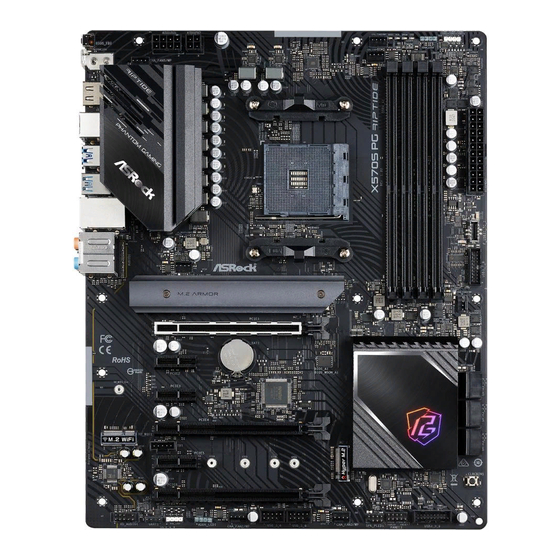
1.3 Motherboard Layout CPU_FAN2/WP ADDR_LED2 RGB_LED2 BOOT DRAM BIOS _FB1 ATX12V1 CHA_FAN5/WP ATX12V2 CPU_FAN1 USB 3.2 Gen1 T: USB3_1 B: USB3_2 USB 3.2 Gen2 T: USB31_TA_1 B: USB31_TC_1 USB 3.2 Gen1 Top: T: USB3_3 RJ-45 F_USB31_TC_1 B: USB3_4 CHA_FAN1/WP CHA_FAN4/WP PCIE1 CMOS PCIE2... - Page 15 X570S PG Riptide No. Description 8 pin 12V Power Connector (ATX12V1) 4 pin 12V Power Connector (ATX12V2) CPU Fan Connector (CPU_FAN1) CPU / Waterpump Fan Connector (CPU_FAN2/WP) 2 x 288-pin DDR4 DIMM Slots (DDR4_A1, DDR4_B1) Post Status Checker (PSC) 2 x 288-pin DDR4 DIMM Slots (DDR4_A2, DDR4_B2)
-
Page 16: I/O Panel
1.4 I/O Panel No. Description No. Description USB 2.0 Ports (USB12) USB 3.2 Gen1 Ports (USB3_34) 2.5G LAN RJ-45 Port* USB 3.2 Gen2 Type-A Port (USB31_TA_1)*** Central / Bass (Orange) USB 3.2 Gen2 Type-C Port (USB31_TC_1) Rear Speaker (Black) USB 3.2 Gen1 Ports (USB3_12)*** Line In (Light Blue) PS/2 Mouse/Keyboard Port (PS2_KB1) Front Speaker (Lime)**... - Page 17 X570S PG Riptide ** If you use a 2-channel speaker, please connect the speaker’s plug into “Front Speaker Jack”. See the table below for connection details in accordance with the type of speaker you use. Audio Output Front Speaker Rear Speaker...
-
Page 18: Graphics Card Holder
1.5 Graphics Card Holder Installing the Graphics Card Holder Before installing the Graphics Card Holder , please make sure that your motherboard is properly installed into a PC case. Step 1 Secure the Graphics Card Holder to the chassis with 2 screws. *There are two types of screws in the package. -
Page 19: Chapter 2 Installation
X570S PG Riptide Chapter 2 Installation This is an ATX form factor motherboard. Before you install the motherboard, study the configuration of your chassis to ensure that the motherboard fits into it. Pre-installation Precautions Take note of the following precautions before you install motherboard components or change any motherboard settings. -
Page 20: Installing The Cpu
2.1 Installing the CPU Unplug all power cables before installing the CPU. - Page 21 X570S PG Riptide...
-
Page 22: Installing The Cpu Fan And Heatsink
2.2 Installing the CPU Fan and Heatsink After you install the CPU into this motherboard, it is necessary to install a larger heatsink and cooling fan to dissipate heat. You also need to spray thermal grease between the CPU and the heatsink to improve heat dissipation. Make sure that the CPU and the heatsink are securely fastened and in good contact with each other. - Page 23 X570S PG Riptide...
- Page 24 Installing the AM4 Box Cooler SR2...
- Page 25 X570S PG Riptide...
- Page 26 *The diagrams shown here are for reference only. The headers might be in a different position on your motherboard.
- Page 27 X570S PG Riptide Installing the AM4 Box Cooler SR3...
- Page 29 X570S PG Riptide +12V *The diagrams shown here are for reference only. The headers might be in a different position on your motherboard.
-
Page 30: Installing Memory Modules (Dimm)
2.3 Installing Memory Modules (DIMM) This motherboard provides four 288-pin DDR4 (Double Data Rate 4) DIMM slots, and supports Dual Channel Memory Technology. 1. For dual channel configuration, you always need to install identical (the same brand, speed, size and chip-type) DDR4 DIMM pairs. 2. - Page 31 X570S PG Riptide Ryzen Series APUs (Renoir): UDIMM Memory Slot Frequency (Mhz) 3200 3200 3200 3200 2933 SR/DR SR/DR 2667 SR/DR SR/DR SR/DR SR/DR 2667 Ryzen Series CPUs (Pinnacle Ridge): UDIMM Memory Slot Frequency (Mhz) 2933 2933 2933 2933 2933...
- Page 32 Ryzen Series APUs (Picasso): UDIMM Memory Slot Frequency (Mhz) 2933 2667 2667 2400 2133 SR/DR SR/DR 1866 SR/DR SR/DR SR/DR SR/DR 1866 SR: Single rank DIMM, 1Rx4 or 1Rx8 on DIMM module label DR: Dual rank DIMM, 2Rx4 or 2Rx8 on DIMM module label...
- Page 33 X570S PG Riptide The DIMM only fits in one correct orientation. It will cause permanent damage to the motherboard and the DIMM if you force the DIMM into the slot at incorrect orientation.
-
Page 34: Expansion Slots (Pci Express Slots)
2.4 Expansion Slots (PCI Express Slots) There are 6 PCI Express slots on the motherboard. Before installing an expansion card, please make sure that the power supply is switched off or the power cord is unplugged. Please read the documentation of the expansion card and make necessary hardware settings for the card before you start the installation. - Page 35 X570S PG Riptide Ryzen series APUs (Picasso) PCIE1 PCIE4 Single Graphics Card Gen3x8 Two Graphics Cards in Gen3x8 Gen4x4 CrossFireX Mode For a better thermal environment, please connect a chassis fan to the motherboard’s chassis fan connector (CHA_FAN1/WP~CHA_FAN5/WP ) when using multiple graphics...
-
Page 36: Onboard Headers And Connectors
2.5 Onboard Headers and Connectors Onboard headers and connectors are NOT jumpers. Do NOT place jumper caps over these headers and connectors. Placing jumper caps over the headers and connectors will cause permanent damage to the motherboard. System Panel Header Connect the power PLED+ PLED-... - Page 37 X570S PG Riptide Power LED and Speaker Please connect the SPEAKER DUMMY Header chassis power LED and DUMMY (7-pin SPK_PLED1) the chassis speaker to this (see p.8, No. 20) header. PLED+ PLED+ PLED- Serial ATA3 Connectors These six SATA3 (SATA3_1: connectors support SATA see p.8, No.
- Page 38 (19-pin USB3_7_8) Vbus Vbus Vbus IntA_PB_SSRX- (see p.8, No. 12) IntA_PA_SSRX- IntA_PB_SSRX+ IntA_PA_SSRX+ IntA_PB_SSTX- IntA_PA_SSTX- IntA_PB_SSTX+ IntA_PA_SSTX+ IntA_PB_D- IntA_PA_D- IntA_PB_D+ IntA_PA_D+ Dummy Front Panel Type C USB There is one Front 3.2 Gen2 Header Panel Type C USB 3.2 (20-pin F_USB31_TC_1) Gen2 Header on this (see p.8, No.
- Page 39 X570S PG Riptide Chassis Water Pump Fan This motherboard Connectors provides five 4-Pin water (4-pin CHA_FAN1/WP) cooling chassis fan (see p.8, No. 29) connectors. If you plan to FAN_SPEED_CONTROL connect a 3-Pin chassis CHA_FAN_SPEED FAN_VOLTAGE water cooler fan, please connect it to Pin 1-3.
- Page 40 ATX Power Connector This motherboard pro- (24-pin ATXPWR1) vides a 24-pin ATX power (see p.8, No. 10) connector. To use a 20-pin ATX power supply, please plug it along Pin 1 and Pin ATX 12V Power This motherboard pro- Connector vides an 8-pin ATX 12V (8-pin ATX12V1) power connector.
- Page 41 X570S PG Riptide Thunderbolt AIC Please connect a Thunderbolt™ Connector add-in card (AIC) to the (5-pin TB1) Thunderbolt AIC connector via (see p.8, No. 28) the GPIO cable. *Please install the Thunderbolt™ AIC card to PCIE3 (default slot). *For the further information, please visit www.asrock.com.
-
Page 42: Smart Buttons
(BIOS_FB1) users to flash the BIOS. (see p.10, No. 16) ASRock BIOS Flashback feature allows you to update BIOS without powering on the system, even without CPU. To use the USB BIOS Flashback function, Please follow the steps below. 1. Download the latest BIOS file from ASRock's website : http://www.asrock.com. - Page 43 X570S PG Riptide USB BIOS Flashback port...
-
Page 44: Post Status Checker
2.7 Post Status Checker Post Status Checker (PSC) diagnoses the computer when users power on the machine. It emits a red light to indicate whether the CPU, memory, VGA or storage is dysfunctional. The lights go off if the four mentioned above are functioning normally. -
Page 45: Tm Tm
X570S PG Riptide 2.8 CrossFireX and Quad CrossFireX Operation Guide This motherboard supports CrossFireX and Quad CrossFireX that allows you to install up to three identical PCI Express x16 graphics cards. 1. You should only use identical CrossFireX -ready graphics cards that are AMD certified. - Page 46 Step 3 Connect a VGA/DVI/DP/HDMI cable from the monitor to the corresponding port on the graphics card installed to the PCIE1 slot.
-
Page 47: Driver Installation And Setup
X570S PG Riptide 2.8.2 Driver Installation and Setup Step 1 Power on your computer and boot into OS. Step 2 Remove the AMD drivers if you have any VGA drivers installed in your system. The Catalyst Uninstaller is an optional download. We recommend using this utility to uninstall any previously installed Catalyst drivers prior to installation. -
Page 48: 2230 Wifi/Bt Pcie Wifi Module Installation
2.9 M.2 2230 WiFi/BT PCIe WiFi module Installation Guide (M2_WIFI) The M.2 Socket (Key E) supports type 2230 WiFi/BT PCIe WiFi module. Installing the 2230 WiFi/BT PCIe WiFi module Step 1 Prepare a type 2230 WiFi/BT PCIe WiFi module and the screw. Step 2 Find the nut location to be used. - Page 49 X570S PG Riptide Step 4 Tighten the screw with a screwdriver to secure the module into place. Please do not overtighten the screw as this might damage the module.
-
Page 50: M.2_Ssd (Ngff) Module Installation Guide (M2_1)
2.10 M.2_SSD (NGFF) Module Installation Guide (M2_1) The M.2, also known as the Next Generation Form Factor (NGFF), is a small size and versatile card edge connector that aims to replace mPCIe and mSATA. The Hyper M.2 Socket (M2_1) supports M Key type 2230/2242/2260/2280 M.2 PCI Express module up to Gen4x4 (64 Gb/s) (with Vermeer, Matisse) or Gen3x4 (32 Gb/s) (with Renoir, Pinnacle Ridge and Picasso). - Page 51 X570S PG Riptide Step 3 Before installing a M.2 (NGFF) SSD module, please loosen the screws to remove the M.2 heatsink. *Please remove the protective films on the bottom side of the M.2 heatsink before you install a M.2 SSD module.
- Page 52 Step 6 Tighten the screw with a screwdriver to secure the module and M.2 heatsink into place. Please do not overtighten the screw as this might damage the module and M.2 heatsink.
- Page 53 X570S PG Riptide M.2_SSD (NGFF) Module Support List (M2_1) Vendor Interface SanDisk PCIe SanDisk-SD6PP4M-128G( Gen2 x2) Intel PCIe INTEL 6000P-SSDPEKKF256G7 (nvme) Intel PCIe INTEL 6000P-SSDPEKKF512G7 (nvme) Intel PCIe SSDPEKKF512G7 NVME / 512GB Kingston PCIe Kingston SHPM2280P2 / 240G (Gen2 x4)
-
Page 54: M.2_Ssd (Ngff) Module Installation Guide (M2_2)
2.11 M.2_SSD (NGFF) Module Installation Guide (M2_2) The M.2, also known as the Next Generation Form Factor (NGFF), is a small size and versatile card edge connector that aims to replace mPCIe and mSATA. The Hyper M.2 Socket (M2_2) supports M Key type 2230/2242/2260/2280 M.2 SATA3 6.0 Gb/s module and M.2 PCI Express module up to Gen4x4 (64 Gb/s). - Page 55 X570S PG Riptide Step 3 Move the standoff based on the module type and length. The standoff is placed at the nut location C by default. Skip Step 3 and 4 and go straight to Step 5 if you are going to use the default nut.
- Page 56 Transcend TS256GMTS800-256GB Transcend SATA TS512GMTS800 / 512GB V-Color SATA V-Color 120G V-Color SATA V-Color 240G SATA WD GREEN WDS240G1G0B-00RC30 PCIe WDS512G1X0C-00ENX0 (NVME) / 512GB For the latest updates of M.2_SSD (NFGG) module support list, please visit our website for details: http://www.asrock.com...
-
Page 57: Chapter 3 Software And Utilities Operation
X570S PG Riptide Chapter 3 Software and Utilities Operation 3.1 Installing Drivers The Support CD that comes with the motherboard contains necessary drivers and useful utilities that enhance the motherboard’s features. Running The Support CD To begin using the support CD, insert the CD into your CD-ROM drive. The CD automatically displays the Main Menu if “AUTORUN”... -
Page 58: Asrock Motherboard Utility (Phantom Gaming Tuning)
Gaming Tuning) ASRock Motherboard Utility (Phantom Gaming Tuning) can be downloaded from ASRock Live Update & APP Shop. After the installation, you will find the icon “AS- Rock Motherboard Utility (Phantom Gaming Tuning)“ on your desktop. Double- click the “ASRock Motherboard Utility (Phantom Gaming Tuning)“... - Page 59 X570S PG Riptide OC Tweaker Configurations for overclocking the system. System Info View information about the system. *The System Browser tab may not appear for certain models.
- Page 60 Settings Configure ASRock ASRock Motherboard Utility (Phantom Gaming Tuning). Click to select "Auto run at Windows Startup" if you want ASRock Motherboard Utility (Phantom Gaming Tuning) to be launched when you start up the Windows operating system.
-
Page 61: Asrock Live Update & App Shop
Double-click on your desktop to access ASRock Live Update & APP Shop utility. *You need to be connected to the Internet to download apps from the ASRock Live Update & APP Shop. 3.3.1 UI Overview Category Panel Hot News... -
Page 62: Apps
3.3.2 Apps When the "Apps" tab is selected, you will see all the available apps on screen for you to download. Installing an App Step 1 Find the app you want to install. The most recommended app appears on the left side of the screen. The other various apps are shown on the right. - Page 63 X570S PG Riptide Step 3 If you want to install the app, click on the red icon to start downloading. Step 4 When installation completes, you can find the green "Installed" icon appears on the upper right corner. To uninstall it, simply click on the trash can icon...
- Page 64 Upgrading an App You can only upgrade the apps you have already installed. When there is an available new version for your app, you will find the mark of "New Version" appears below the installed app icon. Step 1 Click on the app icon to see more details. Step 2 Click on the yellow icon to start upgrading.
-
Page 65: Bios & Drivers
X570S PG Riptide 3.3.3 BIOS & Drivers Installing BIOS or Drivers When the "BIOS & Drivers" tab is selected, you will see a list of recommended or critical updates for the BIOS or drivers. Please update them all soon. Step 1 Please check the item information before update. -
Page 66: Setting
3.3.4 Setting In the "Setting" page, you can change the language, select the server location, and determine if you want to automatically run the ASRock Live Update & APP Shop on Windows startup. -
Page 67: Nahimic Audio
X570S PG Riptide 3.4 Nahimic Audio Nahimic audio software provides an incredible high definition sound technology which boosts the audio and voice performance of your system. Nahimic Audio interface is composed of four tabs : Audio, Microphone, Sound Tracker and Settings. -
Page 68: Asrock Polychrome Sync
3.5 ASRock Polychrome SYNC ASRock Polychrome SYNC is a lighting control utility specifically designed for unique indi- viduals with sophisticated tastes to build their own stylish colorful lighting system. Simply by connecting the LED strip, you can customize various lighting schemes and patterns, including Static, Breathing, Strobe, Cycling, Music, Wave and more. - Page 69 X570S PG Riptide Connecting the Addressable RGB LED Strip Connect your Addressable RGB LED strips to the Addressable LED Headers (ADDR_LED1, ADDR_LED2) on the motherboard. ADDR_LED2 DO_ADDR VOUT ADDR_LED1 DO_ADDR VOUT 1. Never install the RGB LED cable in the wrong orientation; otherwise, the cable may be damaged.
- Page 70 ASRock Polychrome SYNC Utility Now you can adjust the RGB LED color through the ASRock Polychrome SYNC Utility. Download this utility from the ASRock Live Update & APP Shop and start coloring your PC style your way! Drag the tab to customize your preference.
-
Page 71: Chapter 4 Uefi Setup Utility
X570S PG Riptide Chapter 4 UEFI SETUP UTILITY 4.1 Introduction This section explains how to use the UEFI SETUP UTILITY to configure your system. You may run the UEFI SETUP UTILITY by pressing <F2> or <Del> right after you power on the computer, otherwise, the Power-On-Self-Test (POST) will continue with its test routines. -
Page 72: Navigation Keys
4.1.2 Navigation Keys Use < > key or < > key to choose among the selections on the menu bar, and use < > key or < > key to move the cursor up or down to select items, then press <Enter>... -
Page 73: Main Screen
X570S PG Riptide 4.2 Main Screen When you enter the UEFI SETUP UTILITY, the Main screen will appear and display the system overview. -
Page 74: Oc Tweaker Screen
4.3 OC Tweaker Screen In the OC Tweaker screen, you can set up overclocking features. Because the UEFI software is constantly being updated, the following UEFI setup screens and descriptions are for reference purpose only, and they may not exactly match what you see on your screen. - Page 75 X570S PG Riptide SoC/Uncore OC Voltage(VID) Specify the SoC/Uncore voltage (VDD_SOC) in mV to support memory and Infinity Fabric overclocking. VDD_SOC also determines the GPU voltage on processors with integrated graphics. “SoC/Uncore OC Mode” needs to be enabled to force this voltage.
- Page 76 GFX Clock Frequency (Only for processor with integrated graphics) This item allows you to alter the frequency for the GFX clock frequency. After you alter the GFX Clock Frequency settings, make sure to adjust the GFX Core Voltage settings. *The adjustable range is dependent on the CPU being installed. GFX Core Voltage (Only for processor with integrated graphics) This item allows you to alter the voltage for the GFX Core Voltage.
- Page 77 X570S PG Riptide Save User Default Type a profile name and press enter to save your settings as user default. Load User Default Load previously saved user defaults. Save User UEFI Setup Profile to Disk Save current UEFI settings as an user default profile to disk.
-
Page 78: Advanced Screen
4.4 Advanced Screen In this section, you may set the configurations for the following items: CPU Configuration, PCI Configuration, Onboard Devices Configuration, Storage Configuration, ACPI Configuration, Trusted Computing , AMD PBS, AMD Overclocking and AMD CBS. Setting wrong values in this section may cause the system to malfunction. UEFI Configuration Active Page on Entry Select the default page when entering the UEFI setup utility. -
Page 79: Cpu Configuration
X570S PG Riptide 4.4.1 CPU Configuration PSS Support Use this to enable or disable the generation of ACPI_PPC, _PSS, and _PCT objects. PCC Adjustment Use this to adjust PState. NX Mode Use this to enable or disable NX mode. SVM Mode When this is set to [Enabled], a VMM (Virtual Machine Architecture)can utilize the additional hardware capabilities provided by AMD-V. -
Page 80: Pciconfiguration
4.4.2 PCIConfiguration Above 4G Decoding Enable or disable 64bit capable Devices to be decoded in Above 4G Address Space (only if the system supports 64 bit PCI decoding). Re-Size BAR Support If the system has Re-Sizable BAR capable PCIe devices, this option enable or disable the Re-Sizable BAR support. -
Page 81: Onboard Devices Configuration
X570S PG Riptide 4.4.3 Onboard Devices Configuration Turn On Onboard LED in S5 Turn on/off the LED in the ACPI S5 state. Restore Onboard LED Default Restore Onboard LED default value. RGB LED On/Off This option enables/disables the RGB LED. - Page 82 Restore on AC/Power Loss Select the power state after a power failure. If [Power Off] is selected, the power will remain off when the power recovers. If [Power On] is selected, the system will start to boot up when the power recovers. Onboard LAN Enable or disable the onboard network interface controller PS2 Y-Cable...
-
Page 83: Storage Configuration
X570S PG Riptide 4.4.4 Storage Configuration SATA Controller(s) AHCI: Supports new features that improve performance. RAID: Combine multiple disk drives into a logical unit. Chipset SATA Configuration Use this item to configure chipset SATA. -
Page 84: Acpi Configuration
4.4.5 ACPI Configuration Suspend to RAM It is recommended to select auto for ACPI S3 power saving. Deep Sleep Configure deep sleep mode for power saving when the computer is shut down. We recommend disabling Deep Sleep for better system compatibility and stability. PS/2 Keyboard S4/S5 Wakeup Support Allow the system to be waked up by a PS/2 Keyboard in S4/S5. -
Page 85: Trusted Computing
X570S PG Riptide 4.4.6 Trusted Computing Security Device Support Enable or disable BIOS support for security device. -
Page 86: Amd Pbs
4.4.7 AMD PBS The AMD PBS menu accesses AMD specific features. -
Page 87: Amd Overclocking
X570S PG Riptide 4.4.8 AMD Overclocking The AMD Overclocking menu accesses options for configuring CPU frequency and voltage. -
Page 88: Amd Cbs
4.4.9 AMD CBS The AMD CBS menu accesses AMD specific features. -
Page 89: Tools
X570S PG Riptide 4.5 Tools RGB LED ASRock Polychrome SYNC allows you to adjust the RGB LED color to your liking. Easy RAID Installer Easy RAID Installer helps you to copy the RAID driver from the support CD to your USB storage device. After copying the drivers please change the SATA mode to RAID, then you can start installing the operating system in RAID mode. -
Page 90: Hardware Health Event Monitoring Screen
4.6 Hardware Health Event Monitoring Screen This section allows you to monitor the status of the hardware on your system, including the parameters of the CPU temperature, motherboard temperature, fan speed and voltage. CPU_FAN1 Setting Select a fan mode for CPU Fan 1, or choose Customize to set 5 CPU temperatures and assign a respective fan speed for each temperature. - Page 91 X570S PG Riptide CHA_FAN1 / WP Switch Select CHA_FAN1 or Water Pump mode. Chassis Fan 1 Control Mode Select PWM mode or DC mode for Chassis Fan 1. Chassis Fan 1 Setting Select a fan mode for Chassis Fan 1, or choose Customize to set 5 CPU temperatures and assign a respective fan speed for each temperature.
- Page 92 CHA_FAN4 / WP Switch Select CHA_FAN4 or Water Pump mode. Chassis Fan 4 Control Mode Select PWM mode or DC mode for Chassis Fan 4. Chassis Fan 4 Setting Select a fan mode for Chassis Fan 4, or choose Customize to set 5 CPU temperatures and assign a respective fan speed for each temperature.
-
Page 93: Security Screen
X570S PG Riptide 4.7 Security Screen In this section you may set or change the supervisor/user password for the system. You may also clear the user password. Supervisor Password Set or change the password for the administrator account. Only the administrator has authority to change the settings in the UEFI Setup Utility. -
Page 94: Boot Screen
4.8 Boot Screen This section displays the available devices on your system for you to configure the boot settings and the boot priority. Boot From Onboard LAN Allow the system to be waked up by the onboard LAN. Setup Prompt Timeout Configure the number of seconds to wait for the setup hot key. - Page 95 X570S PG Riptide CSM (Compatibility Support Module) Enable to launch the Compatibility Support Module. Please do not disable unless you’re running a WHCK test. Launch PXE OpROM Policy Select UEFI only to run those that support UEFI option ROM only. Select Legacy only to run those that support legacy option ROM only.
-
Page 96: Exit Screen
4.9 Exit Screen Save Changes and Exit When you select this option the following message, “Save configuration changes and exit setup?” will pop out. Select [OK] to save changes and exit the UEFI SETUP UTILITY. Discard Changes and Exit When you select this option the following message, “Discard changes and exit setup?”... - Page 97 Contact Information If you need to contact ASRock or want to know more about ASRock, you’re welcome to visit ASRock’s website at http://www.asrock.com; or you may contact your dealer for further information. For technical questions, please submit a support request form at https://event.asrock.com/tsd.asp...
- Page 98 13848 Magnolia Ave, Chino, CA91710 Phone/Fax No: +1-909-590-8308/+1-909-590-1026 hereby declares that the product Product Name : Motherboard X570S PG Riptide Model Number : Conforms to the following speci cations: FCC Part 15, Subpart B, Unintentional Radiators Supplementary Information: is device complies with part 15 of the FCC Rules. Operation is subject to the...
- Page 99 EU Declaration of Conformity For the following equipment: Motherboard (Product Name) X570S PG Riptide / ASRock (Model Designation / Trade Name) ASRock Incorporation (Manufacturer Name) 2F., No.37, Sec. 2, Jhongyang S. Rd., Beitou District, Taipei City 112, Taiwan (R.O.C.) (Manufacturer Address) EMC —Directive 2014/30/EU (from April 20th, 2016)
Need help?
Do you have a question about the X570S PG Riptide and is the answer not in the manual?
Questions and answers