Table of Contents
Advertisement
Advertisement
Table of Contents

Related Manuals for ASROCK X570 Steel Legend


Summary of Contents for ASROCK X570 Steel Legend
- Page 2 (including damages for loss of profits, loss of business, loss of data, interruption of business and the like), even if ASRock has been advised of the possibility of such damages arising from any defect or error in the documentation or product.
- Page 3 If you require assistance please call ASRock Tel : +886-2-28965588 ext.123 (Standard International call charges apply) The terms HDMI®...
-
Page 4: Table Of Contents
Contents Chapter 1 Introduction Package Contents Specifications Motherboard Layout I/O Panel Block Diagram Chapter 2 Installation Installing the CPU Installing the CPU Fan and Heatsink Installing Memory Modules (DIMM) Expansion Slots (PCI Express Slots) Jumpers Setup Onboard Headers and Connectors Post Status Checker CrossFireX and Quad CrossFireX... - Page 5 Chapter 3 Software and Utilities Operation Installing Drivers A-Tuning 3.2.1 Installing A-Tuning 3.2.2 Using A-Tuning ASRock Live Update & APP Shop 3.3.1 UI Overview 3.3.2 Apps 3.3.3 BIOS & Drivers 3.3.4 Setting ASRock Polychrome SYNC Chapter 4 UEFI SETUP UTILITY Introduction 4.1.1...
- Page 6 4.4.7 AMD CBS 4.4.8 AMD PBS 4.4.9 AMD Overclocking Tools Hardware Health Event Monitoring Screen Security Screen Boot Screen Exit Screen...
-
Page 7: Chapter 1 Introduction
If you require technical support related to this mother- board, please visit our website for specific information about the model you are using. You may find the latest VGA cards and CPU support list on ASRock’s website as well. ASRock website http://www.asrock.com. -
Page 8: Specifications
* For Ryzen Series CPUs (Picasso), ECC is only supported with PRO CPUs. * Please refer to Memory Support List on ASRock’s website for more information. (http://www.asrock.com/) * Please refer to page 25 for DDR4 UDIMM maximum frequency support. - Page 9 X570 Steel Legend AMD Ryzen series CPUs (Pinnacle Ridge) • 2 x PCI Express 3.0 x16 Slots (single at x16 (PCIE1); dual at x16 (PCIE1) / x4 (PCIE4))* AMD Ryzen series CPUs (Picasso) • 2 x PCI Express 3.0 x16 Slots (single at x8 (PCIE1); dual at x8...
- Page 10 Audio • 7.1 CH HD Audio with Content Protection (Realtek ALC1220 Audio Codec) • Premium Blu-ray Audio support • Supports Surge Protection • Supports Purity Sound - Nichicon Fine Gold Series Audio Caps - 120dB SNR DAC with Differential Amplifier - NE5532 Premium Headset Amplifier for Front Panel Audio Connector (Supports up to 600 Ohm headsets) - Pure Power-In...
- Page 11 2230/2242/2260/2280/22110 M.2 SATA3 6.0 Gb/s module and M.2 PCI Express module up to Gen4x4 (64 Gb/s)* * Supports NVMe SSD as boot disks * Supports ASRock U.2 Kit Connector • 1 x TPM Header • 1 x SPI TPM Header • 1 x Power LED and Speaker Header...
- Page 12 • 1 x Front Panel Audio Connector (15μ Gold Audio Connector) • 1 x AMD LED Fan USB Header • 1 x Thunderbolt AIC Connector (5-pin) (Supports ASRock Thunderbolt AIC Card only) • 2 x USB 2.0 Headers (Support 4 USB 2.0 ports) (Supports ESD Protection) • 2 x USB 3.2 Gen1 Headers (Support 4 USB 3.2 Gen1 ports)
- Page 13 • ErP/EuP ready (ErP/EuP ready power supply is required) * For detailed product information, please visit our website: http://www.asrock.com Please realize that there is a certain risk involved with overclocking, including adjusting the setting in the BIOS, applying Untied Overclocking Technology, or using third-party overclocking tools.
-
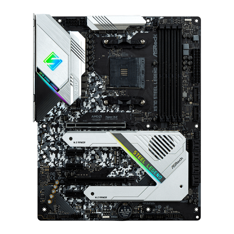
Page 14: Motherboard Layout
1.3 Motherboard Layout AMD_FAN_LED1 CPU_FAN2/WP ATX12V1 ATX12V2 CPU_FAN1 USB 3.2 Gen1 T: USB3 B: USB4 USB 3.2 Gen2 T: USB31_TA_1 B: USB31_TC_1 USB 3.2 Gen1 Top: T: USB5 RJ-45 B: USB6 CHA_FAN1/WP USB_5 SPI_TPM_J1 BIOS PCIE1 CHA_FAN4/WP PCIE2 Premium X570 PCIE3 Purity PCIE4... - Page 15 X570 Steel Legend No. Description 8 pin 12V Power Connector (ATX12V1) 4 pin 12V Power Connector (ATX12V2) CPU Fan Connector (CPU_FAN1) CPU / Waterpump Fan Connector (CPU_FAN2/WP) 2 x 288-pin DDR4 DIMM Slots (DDR4_A1, DDR4_B1) 2 x 288-pin DDR4 DIMM Slots (DDR4_A2, DDR4_B2)
-
Page 16: I/O Panel
1.4 I/O Panel No. Description No. Description PS/2 Mouse/Keyboard Port Antenna Bracket (on I/O Panel Shield) LAN RJ-45 Port* USB 3.2 Gen1 Ports (USB3_56)*** Central / Bass (Orange) USB 3.2 Gen2 Type-A Port (USB31_TA_1) Rear Speaker (Black) USB 3.2 Gen2 Type-C Port (USB31_TC_1) Line In (Light Blue) USB 3.2 Gen1 Ports (USB3_34) Front Speaker (Lime)**... - Page 17 X570 Steel Legend * There are two LEDs on each LAN port. Please refer to the table below for the LAN port LED indications. ACT/LINK LED SPEED LED LAN Port Activity / Link LED Speed LED Status Description Status Description...
-
Page 18: Block Diagram
** If you use a 2-channel speaker, please connect the speaker’s plug into “Front Speaker Jack”. See the table below for connection details in accordance with the type of speaker you use. Audio Output Front Speaker Rear Speaker Central / Bass Line In Channels (No. -
Page 19: Chapter 2 Installation
X570 Steel Legend Chapter 2 Installation This is an ATX form factor motherboard. Before you install the motherboard, study the configuration of your chassis to ensure that the motherboard fits into it. Pre-installation Precautions Take note of the following precautions before you install motherboard components or change any motherboard settings. -
Page 20: Installing The Cpu
2.1 Installing the CPU Unplug all power cables before installing the CPU. - Page 21 X570 Steel Legend...
-
Page 22: Installing The Cpu Fan And Heatsink
2.2 Installing the CPU Fan and Heatsink After you install the CPU into this motherboard, it is necessary to install a larger heatsink and cooling fan to dissipate heat. You also need to spray thermal grease between the CPU and the heatsink to improve heat dissipation. Make sure that the CPU and the heatsink are securely fastened and in good contact with each other. - Page 23 X570 Steel Legend...
- Page 24 Installing the AM4 Box Cooler SR2...
- Page 25 X570 Steel Legend...
- Page 26 4-pin FAN cable RGB LED Cable +12V *The diagrams shown here are for reference only. The headers might be in a different position on your motherboard. Please refer to page 35 for the orientation of AMD Fan LED Header (AMD_ FAN_LED1).
- Page 27 X570 Steel Legend Installing the AM4 Box Cooler SR3...
- Page 29 X570 Steel Legend...
- Page 30 +12V Please note that only one cable should be used at a time in this step. If you select AMD_FAN_LED1, please install ASRock utility "ASRock Polychrome SYNC". If you select USB connector, please install AMD utility "SR3 Settings Software". *The diagrams shown here are for reference only. The headers might be in a different position on your motherboard.
-
Page 31: Installing Memory Modules (Dimm)
X570 Steel Legend 2.3 Installing Memory Modules (DIMM) This motherboard provides four 288-pin DDR4 (Double Data Rate 4) DIMM slots, and supports Dual Channel Memory Technology. 1. For dual channel configuration, you always need to install identical (the same brand, speed, size and chip-type) DDR4 DIMM pairs. - Page 32 Ryzen Series CPUs (Picasso): UDIMM/SO-DIMMs Memory Slot # of DIMMs on # of Ranks 1.20V the Channel per DIMM SR: 2933 1 of 1 DR: 2677 SR: 2667 1 of 2 xR-0 DR: 2400 2 of 2 1R-1R 2133 2 of 2 2R-xR 1866 x=1 or 2...
- Page 33 X570 Steel Legend The DIMM only fits in one correct orientation. It will cause permanent damage to the motherboard and the DIMM if you force the DIMM into the slot at incorrect orientation.
-
Page 34: Expansion Slots (Pci Express Slots)
2.4 Expansion Slots (PCI Express Slots) There are 5 PCI Express slots on the motherboard. Before installing an expansion card, please make sure that the power supply is switched off or the power cord is unplugged. Please read the documentation of the expansion card and make necessary hardware settings for the card before you start the installation. -
Page 35: Jumpers Setup
X570 Steel Legend 2.5 Jumpers Setup The illustration shows how jumpers are setup. When the jumper cap is placed on the pins, the jumper is “Short”. If no jumper cap is placed on the pins, the jumper is “Open”. Clear CMOS Jumper... -
Page 36: Onboard Headers And Connectors
2.6 Onboard Headers and Connectors Onboard headers and connectors are NOT jumpers. Do NOT place jumper caps over these headers and connectors. Placing jumper caps over the headers and connectors will cause permanent damage to the motherboard. System Panel Header Connect the power PLED+ PLED-... - Page 37 X570 Steel Legend Power LED and Speaker Please connect the SPEAKER DUMMY Header chassis power LED and DUMMY (7-pin SPK_PLED1) the chassis speaker to this (see p.8, No. 18) header. PLED+ PLED+ PLED- Serial ATA3 Connectors These eight SATA3 (SATA3_1_2: connectors support SATA see p.8, No.
- Page 38 Front Panel Audio Header This header is for PRESENCE# (9-pin HD_AUDIO1) connecting audio devices MIC_RET OUT_RET (see p.8, No. 29) to the front audio panel. OUT2_L J_SENSE OUT2_R MIC2_R MIC2_L 1. High Definition Audio supports Jack Sensing, but the panel wire on the chassis must sup- port HDA to function correctly.
- Page 39 X570 Steel Legend CPU Fan Connector This motherboard pro- FAN_SPEED_CONTROL CPU_FAN_SPEED (4-pin CPU_FAN1) vides a 4-Pin CPU fan FAN_VOLTAGE (see p.8, No. 3) (Quiet Fan) connector. If you plan to connect a 3-Pin CPU fan, please connect it to Pin 1-3.
- Page 40 (see p.8, No. 27) the GPIO cable. *Please install the Thunderbolt™ AIC card to PCIE4 (default slot). *For the further information, please visit www.asrock.com. LPC/TPM Header This connector supports Trusted (17-pin TPMS1) Platform Module (TPM) system, (see p.8, No. 28)
- Page 41 X570 Steel Legend AMD FAN LED Header AMD FAN LED Header is used (4-pin AMD_FAN_ to connect RGB LED LED1) extension cable that comes with (see p.8, No. 7) AMD heatsink. The cable connection allows users to choose from various LED lighting effects.
-
Page 42: Post Status Checker
2.7 Post Status Checker Post Status Checker (PSC) diagnoses the computer when users power on the machine. It emits a red light to indicate whether the CPU, memory, VGA or stor- age is dysfunctional. The lights go off if the four mentioned above are functioning normally. -
Page 43: Tm Tm
X570 Steel Legend 2.8 CrossFireX and Quad CrossFireX Operation Guide This motherboard supports CrossFireX and Quad CrossFireX that allows you to install up to two identical PCI Express x16 graphics cards. 1. You should only use identical CrossFireX -ready graphics cards that are AMD certified. - Page 44 Step 3 Connect a VGA cable or a DVI cable to the monitor connector or the DVI connec- tor of the graphics card that is inserted to PCIE1 slot.
-
Page 45: Driver Installation And Setup
X570 Steel Legend 2.8.2 Driver Installation and Setup Step 1 Power on your computer and boot into OS. Step 2 Remove the AMD drivers if you have any VGA drivers installed in your system. The Catalyst Uninstaller is an optional download. We recommend using this utility to un- install any previously installed Catalyst drivers prior to installation. -
Page 46: Wifi/Bt Module Installation Guide
2.9 M.2 WiFi/BT Module Installation Guide The M.2 Socket (Key E) supports type 2230 WiFi/BT module. Installing the WiFi/BT module Step 1 Prepare a type 2230 WiFi/BT module and the screw. Step 2 Find the nut location to be used. PCB Length: 3cm Module Type: Type2230 Step 3... - Page 47 X570 Steel Legend Step 4 Tighten the screw with a screwdriver to secure the module into place. Please do not overtighten the screw as this might damage the module.
-
Page 48: M.2_Ssd (Ngff) Module Installation Guide (M2_1)
2.10 M.2_SSD (NGFF) Module Installation Guide (M2_1) The M.2, also known as the Next Generation Form Factor (NGFF), is a small size and versatile card edge connector that aims to replace mPCIe and mSATA. The M.2 Socket (M2_1) supports M Key type 2230/2242/2260/2280 M.2 PCI Express module up to Gen4x4 (64 Gb/s) (with Matisse) or Gen3x4 (32 Gb/s) (with Pinnacle Ridge and Picasso). - Page 49 X570 Steel Legend Step 3 Before installing a M.2 (NGFF) SSD module, please loosen the screws to remove the M.2 heatsink. *Please remove the protective films on the bottom side of the M.2 heatsink before you install a M.2 SSD module.
- Page 50 ASX8000NP-512GM-C / 512GB ADATA PCIe ASX7000NP-512GT-C / 512GB Kingston PCIe SKC1000/480G Kingston PCIe SKC1000/960GB NVME PLEXTOR PCIe PX-512M8PeG/ 512GB PCIe WDS512G1X0C-00ENX0 (NVME) / 512GB For the latest updates of M.2_SSD (NFGG) module support list, please visit our website for details: http://www.asrock.com...
- Page 51 X570 Steel Legend 2.11 M.2_SSD (NGFF) Module Installation Guide (M2_2) The M.2, also known as the Next Generation Form Factor (NGFF), is a small size and versatile card edge connector that aims to replace mPCIe and mSATA. The Hyper M.2 Socket (M2_2) supports M Key type 2230/2242/2260/2280/22110 M.2 SATA3 6.0 Gb/s...
- Page 52 Step 3 Before installing a M.2 (NGFF) SSD module, please loosen the screws to remove the M.2 heatsink. *Please remove the protective films on the bottom side of the M.2 heatsink before you install a M.2 SSD module. Step 4 Prepare the M.2 standoff that comes with the package.
- Page 53 X570 Steel Legend M.2_SSD (NGFF) Module Support List Vendor Interface SanDisk PCIe SanDisk-SD6PP4M-128G( Gen2 x2) Intel PCIe INTEL 6000P-SSDPEKKF256G7 (nvme) Intel PCIe INTEL 6000P-SSDPEKKF512G7 (nvme) Intel PCIe SSDPEKKF512G7 NVME / 512GB Intel SATA 540S-SSDSCKKW240H6 / 240GB Kingston PCIe Kingston SHPM2280P2 / 240G (Gen2 x4)
-
Page 54: Chapter 3 Software And Utilities Operation
Chapter 3 Software and Utilities Operation 3.1 Installing Drivers The Support CD that comes with the motherboard contains necessary drivers and useful utilities that enhance the motherboard’s features. Running The Support CD To begin using the support CD, insert the CD into your CD-ROM drive. The CD automatically displays the Main Menu if “AUTORUN”... -
Page 55: A-Tuning
X570 Steel Legend 3.2 A-Tuning A-Tuning is ASRock’s multi purpose software suite with a new interface, more new features and improved utilities. 3.2.1 Installing A-Tuning A-Tuning can be downloaded from ASRock Live Update & APP Shop. After the installation, you will find the icon “A-Tuning“ on your desktop. Double-click the “A-Tuning“... - Page 56 OC Tweaker Configurations for overclocking the system. System Info View information about the system. *The System Browser tab may not appear for certain models.
- Page 57 Configure up to five different fan speeds using the graph. The fans will automatically shift to the next speed level when the assigned temperature is met. Settings Configure ASRock A-Tuning. Click to select "Auto run at Windows Startup" if you want A-Tuning to be launched when you start up the Windows operating system.
-
Page 58: Asrock Live Update & App Shop
Double-click on your desktop to access ASRock Live Update & APP Shop utility. *You need to be connected to the Internet to download apps from the ASRock Live Update & APP Shop. 3.3.1 UI Overview Category Panel Hot News... -
Page 59: Apps
X570 Steel Legend 3.3.2 Apps When the "Apps" tab is selected, you will see all the available apps on screen for you to download. Installing an App Step 1 Find the app you want to install. The most recommended app appears on the left side of the screen. The other various apps are shown on the right. - Page 60 Step 3 If you want to install the app, click on the red icon to start downloading. Step 4 When installation completes, you can find the green "Installed" icon appears on the upper right corner. To uninstall it, simply click on the trash can icon *The trash icon may not appear for certain apps.
- Page 61 X570 Steel Legend Upgrading an App You can only upgrade the apps you have already installed. When there is an available new version for your app, you will find the mark of "New Version" appears below the installed app icon.
-
Page 62: Bios & Drivers
3.3.3 BIOS & Drivers Installing BIOS or Drivers When the "BIOS & Drivers" tab is selected, you will see a list of recommended or critical updates for the BIOS or drivers. Please update them all soon. Step 1 Please check the item information before update. Click on to see more details. -
Page 63: Setting
X570 Steel Legend 3.3.4 Setting In the "Setting" page, you can change the language, select the server location, and determine if you want to automatically run the ASRock Live Update & APP Shop on Windows startup. -
Page 64: Asrock Polychrome Sync
3.4 ASRock Polychrome SYNC ASRock Polychrome SYNC is a lighting control utility specifically designed for unique indi- viduals with sophisticated tastes to build their own stylish colorful lighting system. Simply by connecting the LED strip, you can customize various lighting schemes and patterns, including Static, Breathing, Strobe, Cycling, Music, Wave and more. - Page 65 X570 Steel Legend Connecting the Addressable RGB LED Strip Connect your Addressable RGB LED strip to the Addressable LED Header (ADDR_LED1) on the motherboard. ADDR_LED1 DO_ADDR VOUT 1. Never install the RGB LED cable in the wrong orientation; otherwise, the cable may be damaged.
- Page 66 ASRock Polychrome SYNC Utility Now you can adjust the RGB LED color through the ASRock RGB LED utility. Download this utility from the ASRock Live Update & APP Shop and start coloring your PC style your way! Drag the tab to customize your preference.
-
Page 67: Chapter 4 Uefi Setup Utility
X570 Steel Legend Chapter 4 UEFI SETUP UTILITY 4.1 Introduction This section explains how to use the UEFI SETUP UTILITY to configure your system. You may run the UEFI SETUP UTILITY by pressing <F2> or <Del> right after you power on the computer, otherwise, the Power-On-Self-Test (POST) will continue with its test routines. -
Page 68: Navigation Keys
4.1.2 Navigation Keys Use < > key or < > key to choose among the selections on the menu bar, and use < > key or < > key to move the cursor up or down to select items, then press <Enter>... -
Page 69: Main Screen
X570 Steel Legend 4.2 Main Screen When you enter the UEFI SETUP UTILITY, the Main screen will appear and display the system overview. -
Page 70: Oc Tweaker Screen
4.3 OC Tweaker Screen In the OC Tweaker screen, you can set up overclocking features. Because the UEFI software is constantly being updated, the following UEFI setup screens and descriptions are for reference purpose only, and they may not exactly match what you see on your screen. - Page 71 X570 Steel Legend Fabric overclocking. VDD_SOC also determines the GPU voltage on processors with integrated graphics. “SoC/Uncore OC Mode” need to be enabled to force this voltage. SMT Mode This item can be used to disable symmetric multithreading. To re-enable SMT, a power cycle is needed after selecting [Auto].
- Page 72 CPU Vcore Voltage Configure the voltage for the CPU Vcore. CPU Vcore Load-Line Calibration CPU Load-Line Calibration helps prevent CPU voltage droop when the system is under heavy loading. CPU VDDCR_SOC Voltage Configure the voltage for the VID-requested VDDCR_SOC supply level. CPU VDDCR_SOC Load-Line Calibration VDDCR_SOC Load-Line Calibration helps prevent VDDCR_SOC voltage droop when the system is under heavy loading.
- Page 73 X570 Steel Legend Load User Default Load previously saved user defaults. Save User UEFI Setup Profile to Disk Save current UEFI settings as an user default profile to disk. Load User UEFI Setup Profile to Disk Load previously saved user defaults from the disk.
-
Page 74: Advanced Screen
4.4 Advanced Screen In this section, you may set the configurations for the following items: CPU Configuration, Onboard Devices Configuration, Storage Configuration, ACPI Configuration, Super IO Configuration, Trusted Computing , AMD CBS, AMD PBS and AMD Overclocking. Setting wrong values in this section may cause the system to malfunction. UEFI Configuration Active Page on Entry Select the default page when entering the UEFI setup utility. -
Page 75: Cpu Configuration
X570 Steel Legend 4.4.1 CPU Configuration PSS Support Use this to enable or disable the generation of ACPI_PPC, _PSS, and _PCT objects. NX Mode Use this to enable or disable NX mode. SVM Mode When this is set to [Enabled], a VMM (Virtual Machine Architecture)can utilize the additional hardware capabilities provided by AMD-V. -
Page 76: Onboard Devices Configuration
4.4.2 Onboard Devices Configuration SR-IOV Support Enable/disable the SR-IOV (Single Root IO Virtualization Support) if the system has SR-IOV capable PCIe devices. UMA Frame buffer Size (Only for processor with integrated graphics) This item allows you to set the size of the UMA frame buffer. Onboard HD Audio Enable/disable onboard HD audio. - Page 77 X570 Steel Legend WAN Radio Configure the WiFi module's connectivity. BT On/Off Enable/disable the bluetooth. Turn On LED is S5 Turn on/off the LED in the ACPI S5 state. PS2 Y-Cable Enable the PS2 Y-Cable or set this option to Auto.
-
Page 78: Storage Configuration
4.4.3 Storage Configuration... -
Page 79: Acpi Configuration
X570 Steel Legend 4.4.4 ACPI Configuration Suspend to RAM It is recommended to select auto for ACPI S3 power saving. PS/2 Keyboard S4/S5 Wakeup Support Allow the system to be waked up by a PS/2 Keyboard in S4/S5. PCIE Devices Power On Allow the system to be waked up by a PCIE device and enable wake on LAN. - Page 80 USB Power Delivery in Soft Off State (S5) If this option is enabled, the USB port will provide power to your devices even when the system is in Power State S5.
-
Page 81: Trusted Computing
X570 Steel Legend 4.4.6 Trusted Computing Security Device Support Enable or disable BIOS support for security device. -
Page 82: Amd Cbs
4.4.7 AMD CBS The AMD CBS menu accesses AMD specific features. -
Page 83: Amd Pbs
X570 Steel Legend 4.4.8 AMD PBS The AMD PBS menu accesses AMD specific features. -
Page 84: Amd Overclocking
4.4.9 AMD Overclocking The AMD Overclocking menu accesses options for configuring CPU frequency and voltage. -
Page 85: Tools
X570 Steel Legend 4.5 Tools RGB LED ASRock Polychrome SYNC allows you to adjust the RGB LED color to your liking. SSD Secure Erase Tool Use this tool to securely erase SSD. Instant Flash Save UEFI files in your USB storage device and run Instant Flash to update your... -
Page 86: Hardware Health Event Monitoring Screen
4.6 Hardware Health Event Monitoring Screen This section allows you to monitor the status of the hardware on your system, including the parameters of the CPU temperature, motherboard temperature, fan speed and voltage. Fan Tuning Measure Fan Min Duty Cycle. Fan-Tastic Tuning Select a fan mode for CPU Fans 1&2, or choose Customize to set 5 CPU temperatures and assign a respective fan speed for each temperature. - Page 87 X570 Steel Legend CPU Fan 2 Control Mode Select PWM mode or DC mode for CPU Fan 2 . CPU Fan 2 Setting Select a fan mode for CPU Fan 2, or choose Customize to set 5 CPU temperatures and assign a respective fan speed for each temperature.
- Page 88 Chassis Fan 3 Control Mode Select PWM mode or DC mode for Chassis Fan 3 . Chassis Fan 3 Setting Select a fan mode for Chassis Fan 3, or choose Customize to set 5 CPU temperatures and assign a respective fan speed for each temperature. Chassis Fan 3 Temp Source Select a fan temperature source for Chassis Fan 3.
-
Page 89: Security Screen
X570 Steel Legend 4.7 Security Screen In this section you may set or change the supervisor/user password for the system. You may also clear the user password. Supervisor Password Set or change the password for the administrator account. Only the administrator has authority to change the settings in the UEFI Setup Utility. -
Page 90: Boot Screen
4.8 Boot Screen This section displays the available devices on your system for you to configure the boot settings and the boot priority. Fast Boot Fast Boot minimizes your computer's boot time. In fast mode you may not boot from an USB storage device. Boot From Onboard LAN Allow the system to be waked up by the onboard LAN. - Page 91 X570 Steel Legend AddOn ROM Display Enable AddOn ROM Display to see the AddOn ROM messages or configure the AddOn ROM if you've enabled Full Screen Logo. Disable for faster boot speed. CSM (Compatibility Support Module) Enable to launch the Compatibility Support Module. Please do not disable unless you’re running a WHCK test.
-
Page 92: Exit Screen
4.9 Exit Screen Save Changes and Exit When you select this option the following message, “Save configuration changes and exit setup?” will pop out. Select [OK] to save changes and exit the UEFI SETUP UTILITY. Discard Changes and Exit When you select this option the following message, “Discard changes and exit setup?”... - Page 93 Contact Information If you need to contact ASRock or want to know more about ASRock, you’re welcome to visit ASRock’s website at http://www.asrock.com; or you may contact your dealer for further information. For technical questions, please submit a support request form at https://event.asrock.com/tsd.asp...
- Page 94 13848 Magnolia Ave, Chino, CA91710 Phone/Fax No: +1-909-590-8308/+1-909-590-1026 hereby declares that the product Product Name : Motherboard X570 Steel Legend Model Number : Conforms to the following speci cations: FCC Part 15, Subpart B, Unintentional Radiators Supplementary Information: is device complies with part 15 of the FCC Rules. Operation is subject to the...
- Page 95 EU Declaration of Conformity For the following equipment: Motherboard (Product Name) X570 Steel Legend/ ASRock (Model Designation / Trade Name) ASRock Incorporation (Manufacturer Name) 2F., No.37, Sec. 2, Jhongyang S. Rd., Beitou District, Taipei City 112, Taiwan (R.O.C.) (Manufacturer Address) EMC —Directive 2014/30/EU (from April 20th, 2016)
Need help?
Do you have a question about the X570 Steel Legend and is the answer not in the manual?
Questions and answers