Table of Contents
Advertisement
Quick Links
Operations Manual
OM-001-01000-00P-04.0
APS - 1000P Series
Power Converters
2004 by Adaptive Power Systems, Inc. (APSI) • All Rights Reserved • No reproduction without written authorization from APSI.
Entire Contents Copyright
TM
ADAPTIVE Power Systems
Worldwide Supplier of Power Conversion Equipment
Advertisement
Table of Contents

Related Manuals for APS 1000P Series

Summary of Contents for APS 1000P Series
- Page 1 Operations Manual OM-001-01000-00P-04.0 APS - 1000P Series Power Converters ADAPTIVE Power Systems Worldwide Supplier of Power Conversion Equipment 2004 by Adaptive Power Systems, Inc. (APSI) • All Rights Reserved • No reproduction without written authorization from APSI. Entire Contents Copyright...
-
Page 2: Table Of Contents
Mechanical Specifications ............... 2-6 Environmental Specifications ............2-6 Output Surge-Current Capability ............ 2-7 2004 by Adaptive Power Systems, Inc. (APSI) • All Rights Reserved • No reproduction without written authorization from APSI. Entire Contents Copyright APS-1000P Series Operation Manual OM-001-01000-00P-04.0... - Page 3 GPIB External Interface ..............5-10 GPIB Standard Status Data Structure ..........5-11 2004 by Adaptive Power Systems, Inc. (APSI) • All Rights Reserved • No reproduction without written authorization from APSI. Entire Contents Copyright APS-1000P Series Operation Manual OM-001-01000-00P-04.0...
- Page 4 Overview ....................7-1 Introduction ..................7-1 System Design .................. 7-2 APS-1000P Series System Block Diagram ........7-3 2004 by Adaptive Power Systems, Inc. (APSI) • All Rights Reserved • No reproduction without written authorization from APSI. Entire Contents Copyright APS-1000P Series Operation Manual OM-001-01000-00P-04.0...
-
Page 5: Contact Information
17711 Mitchell North • Irvine, CA 92614 USA Telephone: (949) 752-8400 FAX: (949) 756-0838 E-mail: sales@adaptivepower.com Web: http://www.adaptivepower.com 2004 by Adaptive Power Systems, Inc. (APSI) • All Rights Reserved • No reproduction without written authorization from APSI. Entire Contents Copyright APS-1000P Series Operation Manual OM-001-01000-00P-04.0... -
Page 6: Warranty Information
For the period of one (1) year from the date of shipment to the purchaser, APS will either repair or replace, at its sole discretion, any unit returned to the APS factory in Irvine, California. It does not cover damage arising from misuse of the unit or attempted field modifications or repairs. -
Page 7: Chapter 1 Introduction
Overview Chapter 1 contains important information you should read BEFORE attempting to install and power-up your APS-1000P Series Power Converter. The information in this chapter is provided for use by experienced operators. Experienced operators understand the necessity of becoming familiar with, and then observing, life-critical safety and installation issues. -
Page 8: Safety Notices
P-series unit includes a user-specified RS-232 external serial interface or GPIB external parallel interface. The APS-1000P Series of Power Converters have been designed to provide frequency and voltage conversion in a controlled test environment. Both manually adjustable and remotely programmable settings are provided. - Page 9 THE PROTECTION PROVIDED BY THE EQUIPMENT MAY BE IMPAIRED 2004 by Adaptive Power Systems, Inc. (APSI) • All Rights Reserved • No reproduction without written authorization from APSI. Entire Contents Copyright APS-1000P Series Operation Manual 1 - 3 OM-001-01000-00P-04.0...
- Page 10 2004 by Adaptive Power Systems, Inc. (APSI) • All Rights Reserved • No reproduction without written authorization from APSI. Entire Contents Copyright APS-1000P Series Operation Manual 1 - 4 OM-001-01000-00P-04.0...
-
Page 11: Preparation For Installation
If the product has been damaged, please alert the freight company and contact APS or the distributor. Please keep the original box and packing to assist in determining how the damage occurred. -
Page 12: Installation Instructions
TheAC input requirement for the APS Power Converter depends on the configured AC input voltage and total power level of the specific APS 1000 model. For three phase AC input models, the current shown in the table below is for each phase. - Page 13 Please check the unit data plate to verify the voltage is correct. Operating Environment APS-1000P Series Power Converters are designed to operate reliably over a wide range of environmental conditions. Please operate within the following limits: Temperature: 0 C – 40 C (32 F – 104 F) ...
-
Page 14: Example Wiring Diagram
CHAPTER 1 INTRODUCTION Example Wiring Diagram INPUT / OUTPUT Power Panel at Rear of APS Unit (typical) G N C B A OUTPUT CONNECTIONS INPUT CONNECTIONS NOTE: Terminal Phases R, S, T are North American (U.S.) A, B, C NOTE: Other terminal configurations are possible. For example, there is no neutral terminal for 3-phase delta-winding inputs. -
Page 15: Storage And Transportation
Please retain all the original packing materials. If the equipment must be sent back for repair, use the original packing materials for packing. Please contact the APS repair center or factory before returning equipment. Be sure to send all accessories and indicate the symptoms and cause of failure if known. -
Page 16: Chapter 2 Specifications
All units provide built-in PLC remote control for three program memories. At the time of purchase, APS-1000P users select between one of two external control and data interfaces: either RS-232 or GPIB. Both external interfaces provide full input and output control of functions and data, independent of internally stored programs. -
Page 17: Introduction
Introduction APS-1000P Power Converters are rugged versatile workhorses. The intended location for APS-1000P units is the test floor, not a laboratory workbench. The smallest unit, the APS-1002P, weights 177 lbs. The largest unit, the APS-1060P, weighs 1825 lbs. Users can select from several modes of operation: ... -
Page 18: Input Electrical Specifications
Over-Current, Short-Circuit, Over-Temperature Efficiency 85% (at full load) 2004 by Adaptive Power Systems, Inc. (APSI) • All Rights Reserved • No reproduction without written authorization from APSI. Entire Contents Copyright APS-1000P Series Operation Manual 2 - 3 OM-001-01000-00P-04.0... -
Page 19: Isolation Data
Output to Chassis Isolation Working: 600Vac, Max. 945 Vdc for 60 secs 2004 by Adaptive Power Systems, Inc. (APSI) • All Rights Reserved • No reproduction without written authorization from APSI. Entire Contents Copyright APS-1000P Series Operation Manual 2 - 4 OM-001-01000-00P-04.0... -
Page 20: Power Versus Output Frequency Rating Chart
15 minutes then instrument output will shut down because output transformer is too hot. 2004 by Adaptive Power Systems, Inc. (APSI) • All Rights Reserved • No reproduction without written authorization from APSI. Entire Contents Copyright APS-1000P Series Operation Manual 2 - 5 OM-001-01000-00P-04.0... -
Page 21: Displays And Controls
Front Panel Calibration PLC interface controls execution of programmed steps in Memories 1, 2, or 3. (external) The PLC interface is a standard feature of all APS Power Converters. Interface Ext. Data Both RS-232 and GPIB data interfaces allow execution of remote commands. Access to and Interface recording of active test data is possible. -
Page 22: Output Surge-Current Capability
The exact time depends upon the temperature and line conditions. 2004 by Adaptive Power Systems, Inc. (APSI) • All Rights Reserved • No reproduction without written authorization from APSI. Entire Contents Copyright APS-1000P Series Operation Manual 2 - 7 OM-001-01000-00P-04.0... -
Page 23: Unit Description
You need to know the vocabulary of the APS-1000P Series to take full advantage of the information in this manual. Information in this chapter is in three sections: ... - Page 24 CHAPTER 3 UNIT DESCRIPTION 2004 by Adaptive Power Systems, Inc. (APSI) • All Rights Reserved • No reproduction without written authorization from APSI. Entire Contents Copyright APS-1000P Series Operation Manual 3 - 2 OM-001-01000-00P-04.0...
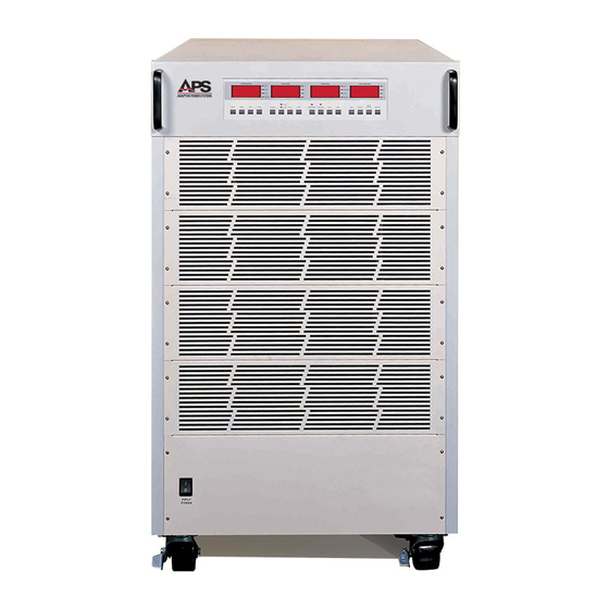
- Page 25 CHAPTER 3 UNIT DESCRIPTION Front Panel of APS-1000P Series Power Converter 2004 by Adaptive Power Systems, Inc. (APSI) • All Rights Reserved • No reproduction without written authorization from APSI. Entire Contents Copyright APS-1000P Series Operation Manual 3 - 3...
- Page 26 Steps the output frequency up to a maximum of 500 Hz. ︿ button 2004 by Adaptive Power Systems, Inc. (APSI) • All Rights Reserved • No reproduction without written authorization from APSI. Entire Contents Copyright APS-1000P Series Operation Manual 3 - 4 OM-001-01000-00P-04.0...
- Page 27 Steps the output voltage up; SYSTEM / PROGRAM parameter select. ︿ button 2004 by Adaptive Power Systems, Inc. (APSI) • All Rights Reserved • No reproduction without written authorization from APSI. Entire Contents Copyright APS-1000P Series Operation Manual 3 - 5 OM-001-01000-00P-04.0...
- Page 28 0.1 to system max. 2004 by Adaptive Power Systems, Inc. (APSI) • All Rights Reserved • No reproduction without written authorization from APSI. Entire Contents Copyright APS-1000P Series Operation Manual 3 - 6 OM-001-01000-00P-04.0...
- Page 29 Switches between the display of P (Power), PF (Power Factor), T (Testing Time), and P-S (Program-Step). 2004 by Adaptive Power Systems, Inc. (APSI) • All Rights Reserved • No reproduction without written authorization from APSI. Entire Contents Copyright APS-1000P Series Operation Manual 3 - 7 OM-001-01000-00P-04.0...
-
Page 30: Cabinet Controls And Connections
See the following page for illustrations. The Cabinet Controls Table on page 3-9 provides additional information about each of these items. Chassis Details The APS-1000P is built on a rugged chassis for use in demanding test environments. Important elements of the design include: Handles ... - Page 31 Circuit Breaker Input Power Output Power Terminals Terminals (see page 1-7) (see page 1-7) APS-1000P Series Unit (typical) Note: The exact configuration of your unit Rear Wheels may be different from the illustration, Fixed Position depending on the model number.
-
Page 32: Cabinet Features
Adequate cooling airflow is essential in maintaining proper operation. 2004 by Adaptive Power Systems, Inc. (APSI) • All Rights Reserved • No reproduction without written authorization from APSI. Entire Contents Copyright APS-1000P Series Operation Manual 3 - 10 OM-001-01000-00P-04.0... -
Page 33: Operating Instructions
Operating Instructions Overview Use the instructions in Chapter 4 to set up your APS-1000P Power Converter so you can conduct tests. However, before attempting to set up your APS unit for testing, you should be familiar with the information provided in Chapters 1, 2, and 3. -
Page 34: Basic Operation
300V range is one-half that in the 150V range. 2004 by Adaptive Power Systems, Inc. (APSI) • All Rights Reserved • No reproduction without written authorization from APSI. Entire Contents Copyright APS-1000P Series Operation Manual 4 - 2 OM-001-01000-00P-04.0... - Page 35 (150V max) range. 2004 by Adaptive Power Systems, Inc. (APSI) • All Rights Reserved • No reproduction without written authorization from APSI. Entire Contents Copyright APS-1000P Series Operation Manual 4 - 3 OM-001-01000-00P-04.0...
- Page 36 Error Messages section of this chapter. 2004 by Adaptive Power Systems, Inc. (APSI) • All Rights Reserved • No reproduction without written authorization from APSI. Entire Contents Copyright APS-1000P Series Operation Manual 4 - 4 OM-001-01000-00P-04.0...
- Page 37 Note: If your unit shuts down due to a detected Over-Current condition, the FREQUENCY display shows OCP. 2004 by Adaptive Power Systems, Inc. (APSI) • All Rights Reserved • No reproduction without written authorization from APSI. Entire Contents Copyright APS-1000P Series Operation Manual 4 - 5 OM-001-01000-00P-04.0...
- Page 38 You can press the RESET button to stop any test at any time. 2004 by Adaptive Power Systems, Inc. (APSI) • All Rights Reserved • No reproduction without written authorization from APSI. Entire Contents Copyright APS-1000P Series Operation Manual 4 - 6 OM-001-01000-00P-04.0...
- Page 39 This procedure is used to avoid accidental adjustments to the system. 2004 by Adaptive Power Systems, Inc. (APSI) • All Rights Reserved • No reproduction without written authorization from APSI. Entire Contents Copyright APS-1000P Series Operation Manual 4 - 7 OM-001-01000-00P-04.0...
- Page 40 For external control, you can also use your installed external RS-232 or GPIB port. Both of these interfaces provide two-way APS-1000P control and data when using an external controller. Please see Chapter 5 for details about using RS-232 and GPIB.
-
Page 41: System Parameter Settings
OPERATING INSTRUCTIONS System Parameter Settings APS-1000P front panel displays are used to present status, test data, and system parameters. This is the normal mode of display during operation. A special operator- selected mode (described below) is entered when using the front panel displays for setting system parameters. -
Page 42: System Parameter Table
Constant Current output mode, ON / OFF 2004 by Adaptive Power Systems, Inc. (APSI) • All Rights Reserved • No reproduction without written authorization from APSI. Entire Contents Copyright APS-1000P Series Operation Manual 4 - 10 OM-001-01000-00P-04.0... -
Page 43: Setting System Parameters (Programming)
The system will power up using the output settings that were active when it was last shut down. 2004 by Adaptive Power Systems, Inc. (APSI) • All Rights Reserved • No reproduction without written authorization from APSI. Entire Contents Copyright APS-1000P Series Operation Manual 4 - 11 OM-001-01000-00P-04.0... - Page 44 The Volt HI value must be higher than the Volt LO value. 2004 by Adaptive Power Systems, Inc. (APSI) • All Rights Reserved • No reproduction without written authorization from APSI. Entire Contents Copyright APS-1000P Series Operation Manual 4 - 12 OM-001-01000-00P-04.0...
- Page 45 Note: The parameter settings for current and power are described in the following section, Program Parameter Settings. 2004 by Adaptive Power Systems, Inc. (APSI) • All Rights Reserved • No reproduction without written authorization from APSI. Entire Contents Copyright APS-1000P Series Operation Manual 4 - 13 OM-001-01000-00P-04.0...
-
Page 46: Program Parameter Settings
PROGRAM (on the CURRENT Display), to leave the Program Parameter Setting mode. 2004 by Adaptive Power Systems, Inc. (APSI) • All Rights Reserved • No reproduction without written authorization from APSI. Entire Contents Copyright APS-1000P Series Operation Manual 4 - 14 OM-001-01000-00P-04.0... -
Page 47: Program Parameter Table
Connect Step enable/disable 2004 by Adaptive Power Systems, Inc. (APSI) • All Rights Reserved • No reproduction without written authorization from APSI. Entire Contents Copyright APS-1000P Series Operation Manual 4 - 15 OM-001-01000-00P-04.0... -
Page 48: Setting Program Parameters (Programming)
(P1 – P8) contains up to 5 steps of different settings. Programmed steps 2004 by Adaptive Power Systems, Inc. (APSI) • All Rights Reserved • No reproduction without written authorization from APSI. Entire Contents Copyright APS-1000P Series Operation Manual 4 - 16 OM-001-01000-00P-04.0... - Page 49 0. This means that the system will begin checking for out-of-range test parameters as soon as the program starts. 2004 by Adaptive Power Systems, Inc. (APSI) • All Rights Reserved • No reproduction without written authorization from APSI. Entire Contents Copyright APS-1000P Series Operation Manual 4 - 17 OM-001-01000-00P-04.0...
- Page 50 0.001 – 1.000. When set to “OFF”, there is no power factor high limit. 2004 by Adaptive Power Systems, Inc. (APSI) • All Rights Reserved • No reproduction without written authorization from APSI. Entire Contents Copyright APS-1000P Series Operation Manual 4 - 18 OM-001-01000-00P-04.0...
- Page 51 40 manually programmed steps to be sequentially executed. 2004 by Adaptive Power Systems, Inc. (APSI) • All Rights Reserved • No reproduction without written authorization from APSI. Entire Contents Copyright APS-1000P Series Operation Manual 4 - 19 OM-001-01000-00P-04.0...
-
Page 52: Error Messages
OPERATING INSTRUCTIONS Error Messages Why are there Errors? Setup mistakes happen. Overloads occur. Systems under test fail. When the APS- 1000P unit encounters a fault condition, an error has occurred. The result is: The front panel display presents a message. - Page 53 CHAPTER 4 OPERATING INSTRUCTIONS 2004 by Adaptive Power Systems, Inc. (APSI) • All Rights Reserved • No reproduction without written authorization from APSI. Entire Contents Copyright APS-1000P Series Operation Manual 4 - 21 OM-001-01000-00P-04.0...
- Page 54 Output voltage was low OPP Output power was high 2004 by Adaptive Power Systems, Inc. (APSI) • All Rights Reserved • No reproduction without written authorization from APSI. Entire Contents Copyright APS-1000P Series Operation Manual 4 - 22 OM-001-01000-00P-04.0...
-
Page 55: Error Message Table
Output voltage below limit Output power exceeded limit 2004 by Adaptive Power Systems, Inc. (APSI) • All Rights Reserved • No reproduction without written authorization from APSI. Entire Contents Copyright APS-1000P Series Operation Manual 4 - 23 OM-001-01000-00P-04.0... -
Page 56: Interpreting Error Messages
VOLTAGE and CURRENT displays will show the corresponding values at the time of overload. 2004 by Adaptive Power Systems, Inc. (APSI) • All Rights Reserved • No reproduction without written authorization from APSI. Entire Contents Copyright APS-1000P Series Operation Manual 4 - 24 OM-001-01000-00P-04.0... - Page 57 DC voltage). This means the INVERTER supply voltage is less than the normal working range for the APS-1000P. An alarm will sound; the FAIL LED will flash; the PROTECT LED will light; and the VOLTAGE and CURRENT displays will show their corresponding values.
- Page 58 PROTECT LED will light; and the VOLTAGE and CURRENT displays will show the corresponding values at the time of over-voltage. 2004 by Adaptive Power Systems, Inc. (APSI) • All Rights Reserved • No reproduction without written authorization from APSI. Entire Contents Copyright APS-1000P Series Operation Manual 4 - 26 OM-001-01000-00P-04.0...
- Page 59 VOLTAGE and CURRENT displays will show the corresponding values at the time of over- power. 2004 by Adaptive Power Systems, Inc. (APSI) • All Rights Reserved • No reproduction without written authorization from APSI. Entire Contents Copyright APS-1000P Series Operation Manual 4 - 27 OM-001-01000-00P-04.0...
-
Page 60: External Interfaces
GPIB External Interface (See Caution) CAUTION DO NOT attempt to command the APS-3000P using the RS-232 or GPIB external interfaces — unless you are an experienced programmer who is thoroughly familiar with real-time operation of programmable test instrumentation. Failure to heed this CAUTION may result in SERIOUS INJURY to test personnel or COSTLY DAMAGE to equipment under test. -
Page 61: Plc External Interface
If the system encounters an error, the front panel RESET button or the ON/OFF control at the PLC remote can be enabled to perform a system reset. A sketch of the APS PLC DE-9 pinouts and simple switch configuration is shown on the following page. -
Page 62: Manual Switcher (Three Program Control)
1N4148 or 1N914, etc. ON / OFF PLC DE-9 Connector and Control 2004 by Adaptive Power Systems, Inc. (APSI) • All Rights Reserved • No reproduction without written authorization from APSI. Entire Contents Copyright APS-1000P Series Operation Manual 5 - 3 OM-001-01000-00P-04.0... -
Page 63: How To Verify Rs-232 Serial Operation
External Interface Installed. If your unit has the GPIB option installed, please turn forward to the GPIB External Interface Section (page 5-10). The RS-232 connector is located at the rear of the APS-1000P (see page 3-8).The 9- pin RS-232 connector is clearly identified, to distinguish it from the (also 9-pin) PLC connector. - Page 64 Remove the jumper. Use a connecting cable. Connecting Cable Locate the identified RS-232 (DE-9) connector on rear panel of the APS unit. CAUTION: DO NOT use the 9-pin (DE-9) PLC connector! Use a cross-connect cable that interconnects receive and transmit lines.
- Page 65 9600 bps, 8 data bits, 1 stop bit, and no parity. There is no complex software protocol. There is no hardware handshaking. Individual instructions or character strings are sent from your computer to the APS unit via the RS-232 connection. Transmitted characters are either accepted or rejected by the APS RS-232 port controller.
-
Page 66: Rs-232 Command And Control Functions
CHAPTER 5 APPLICATIONS RS-232 Command and Control Functions The following three tables list the APS-1000P RS-232 commands and queries: Front Panel and RS-232 Command Functions RS-232 System Control Functions RS-232 Program Functions Front Panel and RS-232 Command Functions... - Page 67 FHI XXX.X FREQ:HI? FHI? FREQ:LO XXX.X FLO XXX.X FREQ:LO? FLO? 2004 by Adaptive Power Systems, Inc. (APSI) • All Rights Reserved • No reproduction without written authorization from APSI. Entire Contents Copyright APS-1000P Series Operation Manual 5 - 8 OM-001-01000-00P-04.0...
- Page 68 CONNECT X 0 = OFF 1 = ON CONNECT? CONNECT? 2004 by Adaptive Power Systems, Inc. (APSI) • All Rights Reserved • No reproduction without written authorization from APSI. Entire Contents Copyright APS-1000P Series Operation Manual 5 - 9 OM-001-01000-00P-04.0...
-
Page 69: Gpib External Interface
APPLICATIONS GPIB External Interface Use the information in this section only if your APS-1000P unit has the GPIB External Interface installed. If your unit has the RS-232 option installed, please turn back to the RS-232 External Interface Section (page 5-4). -
Page 70: Gpib Standard Status Data Structure
Power On *ESR *ESE<NRf> *STB? SPOLL *SRE<NRf> *ESE? *SRE? 2004 by Adaptive Power Systems, Inc. (APSI) • All Rights Reserved • No reproduction without written authorization from APSI. Entire Contents Copyright APS-1000P Series Operation Manual 5 - 11 OM-001-01000-00P-04.0... - Page 71 DIO8, is either unused or used for parity. 2004 by Adaptive Power Systems, Inc. (APSI) • All Rights Reserved • No reproduction without written authorization from APSI. Entire Contents Copyright APS-1000P Series Operation Manual 5 - 12 OM-001-01000-00P-04.0...
- Page 72 GPIB Connectors and Cables Additional connector and cable diagrams are not provided for GPIB. APS assumes you are using high-quality commercial cables and connectors that are essential for obtaining high-speed performance provided by the GPIB bus.
-
Page 73: Gpib Command And Control Functions
CHAPTER 5 APPLICATIONS GPIB Command and Control Functions The following four tables list the APS-1000P Series GPIB commands and queries: Front Panel and GPIB Command Functions GPIB System Control Functions GPIB Program Functions GPIB General Status Queries... -
Page 74: Gpib System Control Functions
FHI XXX.X FREQ:HI? FHI? FREQ:LO XXX.X FLO XXX.X FREQ:LO? FLO? 2004 by Adaptive Power Systems, Inc. (APSI) • All Rights Reserved • No reproduction without written authorization from APSI. Entire Contents Copyright APS-1000P Series Operation Manual 5 - 15 OM-001-01000-00P-04.0... -
Page 75: Gpib Program Functions
CONNECT X 0 = OFF 1 = ON CONNECT? CONNECT? 2004 by Adaptive Power Systems, Inc. (APSI) • All Rights Reserved • No reproduction without written authorization from APSI. Entire Contents Copyright APS-1000P Series Operation Manual 5 - 16 OM-001-01000-00P-04.0... -
Page 76: Gpib Status Queries
Value = 0 / 1 *PSC <value> Power-ON Status Query *PSC? 2004 by Adaptive Power Systems, Inc. (APSI) • All Rights Reserved • No reproduction without written authorization from APSI. Entire Contents Copyright APS-1000P Series Operation Manual 5 - 17 OM-001-01000-00P-04.0... -
Page 77: Chapter 6 System Calibration
Whether you perform calibration prior to a critical test or as a scheduled annual maintenance task, the procedures for calibration are identical. Note, the values of some calibration parameters are different for different sizes of APS models. This chapter includes tables of all calibration parameters for all models. Please use the calibration values that are for your particular model. -
Page 78: Calibration Setup
The High Current Calibration Procedure (later in this chapter) specifies an output voltage of 100 VAC, for all models. From the Table of Calibration Settings, you see the A HI (A) calibration test current for the (example) APS-1010P is specified at 80 A. CALIBRATION SETTINGS... - Page 79 CLEANING SHOULD BE REFERRED TO PERSONNEL AUTHORIZED BY THE FACTORY TO SERVICE THIS EQUIPMENT. 2004 by Adaptive Power Systems, Inc. (APSI) • All Rights Reserved • No reproduction without written authorization from APSI. Entire Contents Copyright APS-1000P Series Operation Manual 6 - 3 OM-001-01000-00P-04.0...
-
Page 80: Calibration Instructions
After about 2 seconds, the unit will execute the calibration program that is appropriate for your particular unit, based on the APS model number. The panel will display the (firmware) version number. XY corresponds to the model number and nominal power rating of your unit. - Page 81 Please refer to page "v" of this manual for factory contact information. 2004 by Adaptive Power Systems, Inc. (APSI) • All Rights Reserved • No reproduction without written authorization from APSI. Entire Contents Copyright APS-1000P Series Operation Manual 6 - 5 OM-001-01000-00P-04.0...
- Page 82 CHAPTER 6 INSTRUMENTATION CALIBRATION Selecting Calibration Parameters Following the controlled power-up, your APS unit enters the Low Voltage ) calibration mode. Press the FREQUENCY ﹀ or ︿ buttons to select the system parameter you are going to calibrate.
-
Page 83: Low-Voltage Mode (V-Lo) Calibration
5. At the MULTIMETER Display, press the LOCK button to finish low-voltage calibration. 6. Proceed to the next calibration function, unless this completes system calibration. 7. Note, to exit the Calibration Mode, your APS system must be restarted after you have completed ALL calibration operations. ... -
Page 84: High-Voltage Mode (V-Hi) Calibration
5. At the MULTIMETER Display, press the LOCK button to finish high-voltage calibration. 6. Proceed to the next calibration function, unless this completes system calibration. 7. Note, to exit the Calibration Mode, your APS system must be restarted after you have completed ALL calibration operations. ... -
Page 85: Low-Current Mode (A-Lo) Calibration
27.00 36.00 54.0 5. At the MULTIMETER Display, press the TEST button. The APS unit will automatically perform a low-current output reading and will output approximately 120 VAC. 6. The external RMS ammeter will display the actual current output. The CURRENT Display shows the calibration value (see Calibration Table, above). - Page 86 CHAPTER 6 INSTRUMENTATION CALIBRATION 10. Proceed to the next calibration function, unless this completes system calibration. 11. Note, to exit the Calibration Mode, your APS system must be restarted after you have completed ALL calibration operations. 2004 by Adaptive Power Systems, Inc. (APSI) • All Rights Reserved • No reproduction without written authorization from APSI.
-
Page 87: High-Current Mode (A-Hi) Calibration
27.00 36.00 54.0 5. At the MULTIMETER Display, press the TEST button. The APS unit will automatically perform a high-current output reading and will output approximately 120 VAC. 6. The external RMS ammeter will display the actual current output. The CURRENT Display shows the calibration value (see Calibration Table, above). - Page 88 CHAPTER 6 INSTRUMENTATION CALIBRATION 10. Proceed to the next calibration function, unless this completes system calibration. 11. Note, to exit the Calibration Mode, your APS system must be restarted after you have completed ALL calibration operations. 2004 by Adaptive Power Systems, Inc. (APSI) • All Rights Reserved • No reproduction without written authorization from APSI.
-
Page 89: Low-Power Mode (P-Lo) Calibration
RMS power meter, of at least 0.2% accuracy. 3. The size of the load should be calculated based on the low-current parameter for your particular APS unit, as shown in the following Calibration Table. Use 120 VAC for the voltage. - Page 90 CHAPTER 6 INSTRUMENTATION CALIBRATION 10. Proceed to the next calibration function, unless this completes system calibration. 11. Note, to exit the Calibration Mode, your APS system must be restarted after you have completed ALL calibration operations. 2004 by Adaptive Power Systems, Inc. (APSI) • All Rights Reserved • No reproduction without written authorization from APSI.
-
Page 91: High-Power Mode P-Hi) Calibration
RMS power meter, of at least 0.2% accuracy. 3. The size the load should be calculated based on the high-current parameter for your particular APS unit, as shown in the following Calibration Table. Use 120 VAC for the voltage. - Page 92 CHAPTER 6 INSTRUMENTATION CALIBRATION 10. Proceed to the next calibration function, unless this completes system calibration. 11. Note, to exit the Calibration Mode, your APS system must be restarted after you have completed ALL calibration operations. 2004 by Adaptive Power Systems, Inc. (APSI) • All Rights Reserved • No reproduction without written authorization from APSI.
-
Page 93: Chapter 7 System Maintenance
Do not modify this equipment. Any modifications void the warranty automatically, and violate the tested safety standards of the unit. APS does not take responsibility for such equipment. Parts or accessories not certified by APS will not be covered under the warranty. -
Page 94: System Design
SERVICABLE INTERNAL PARTS. System Block Diagram If you are interested in how the APS-1000P works, you can learn more by reviewing the System Block Diagram on the following page. Please note, the block diagram is supplied for information purposes only. There are no serviceable components available to the user. -
Page 95: Aps-1000P Series System Block Diagram
Inverter DC Bus Hi / Lo Test Blown Fuse Test Overheat Test APS-1000P Series System Block Diagram 2004 by Adaptive Power Systems, Inc. (APSI) • All Rights Reserved • No reproduction without written authorization from APSI. Entire Contents Copyright...
Need help?
Do you have a question about the 1000P Series and is the answer not in the manual?
Questions and answers