Advertisement
Quick Links
918S, 918D, and 918Q Series Alarms
Installation, Operation, and Maintenance Instructions
918S Single Channel Alarm
The 918S is designed to provide a visible and audible alarm. The 918S may be used anywhere that a single
set of dry contacts are available. The 918S can be configured to respond to either Normally Open (default
configuration) or Normally Closed contacts. Two possible primary applications are used as an overfill alarm or
as an interstitial alarm.
918D Dual Channel Alarm
The 918D is designed to provide a visible and audible alarm. The 918D has two front panel Alarm Indicators to
indicate which channel is being alarmed. The 918D may be used anywhere that up to two sets of dry contacts
are available. The 918D can be configured to respond to either Normally Open (default configuration) or
Normally Closed contacts. Two possible primary applications for each channel are as an overfill alarm or as an
interstitial alarm.
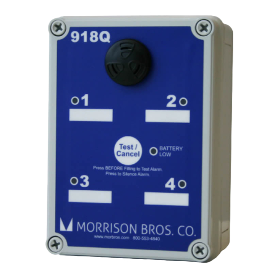
918Q Quad Channel Alarm
The 918Q is designed to provide a visible and audible alarm. The 918Q has four front panel Alarm Indicators to
indicate which channel is being alarmed. The 918Q may be used anywhere that up to four sets of dry contacts
are available. The 918Q can be configured to respond to either Normally Open (default configuration) or
Normally Closed contacts. Two possible primary applications for each channel are as an overfill alarm or as an
interstitial alarm.
!
Failure to follow any or all of the warnings and instructions in this document could result in a hazardous
liquid spill, which could result in property damage, environmental contamination, fire, explosion, serious
injury or death.
!
Le fait de ne pas se conformer à l'un ou l'autre des avertissements ou à l'une ou l'autre des directives
apparaissant dans ce document pourrait donner lieu à des déversements de liquides dangereux, lesquels
pourraient engendrer des dommages matériels, des risques de contamination environnementale,
d'incendie ou d'explosion, des blessures graves ou la mort.
Specifications
The 918S, 918D and 918Q are intrinsically safe devices for use in Class I, Division 1, Group D, T4 and Zone 2,
Group IIA, T4 Hazardous locations when powered by Morrison Bros. Co. battery pack part number
918SB-0128 2B.
WARNING: This is an intrinsically safe device and must be wired in accordance with National Electrical Code
Article 504. This device and its wiring may not share any junction box, conduit, or raceway with any other type
circuit or wiring. Do not perform live maintenance. Do not substitute components with anything other than
Morrison Bros. Co. components. Care must be taken to avoid an ignition hazard from impact or friction with the
enclosure.
AVERTISSEMENT: Cet appareil intrinsèquement sécuritaire doit être branché conformément à l'article
504 du code électrique national. Il se peut que ce dispositif et son câblage ne partagent pas de boîte de
connexion, de conduit ou de canalisation avec un autre type de circuit ou de câblage. Ne menez pas de travaux
de maintenance sous tension. Ne remplacez les composantes que par des composantes de Morrison Bros. Co.
Assurez-vous d'éviter le risque d'infl ammation pouvant découler d'un impact ou de friction avec l'enceinte.
Entity Parameters for Terminals P1 through P4:
V
= 7.525 VDC
OC
Operating Temperature: -40ºF to 140ºF (-40ºC to 60ºC)
Maximum Wiring Distance: Maximum wiring distance between Alarm and input device is 500 ft.
I
= 31 mA
Ca = 700 μF La = 105 μH P
SC
= 0.06 W
O
Morrison Bros. Co. ‑ Dubuque, IA ‑ 800‑553‑4840
918S‑‑1130 PP
1
rev 12‑21‑2020
Advertisement

Related Manuals for Morrison Bros. co. 918S Series


Summary of Contents for Morrison Bros. co. 918S Series
- Page 1 918S, 918D, and 918Q Series Alarms Installation, Operation, and Maintenance Instructions 918S Single Channel Alarm The 918S is designed to provide a visible and audible alarm. The 918S may be used anywhere that a single set of dry contacts are available. The 918S can be configured to respond to either Normally Open (default configuration) or Normally Closed contacts.
- Page 2 Alarm Installation and Testing WArnIngS • Fire Hazard – Death or serious injury could result from spilled liquids. • You must be trained to install or maintain this alarm. Stop now if you have not been trained. • Any modification of this unit beyond what is outlined in this instruction will void product warranty. •...
- Page 3 WARNING: Interconnect wiring between the gauge and the alarm unit must be kept totally isolated and separate from any other wiring. This wiring must not share any junction box, conduit, raceway, or fixtures with circuits other than those defined by NEC as being intrinsically safe for all Class 1 locations. AVERTISSEMENT: Le câblage d’interconnexion entre la jauge et l’unité...
- Page 4 • The Channel Alarm indicators will illuminate when the Audible Alarm is not sounding. If configured for no audible alarm, only the Channel Alarm indicator(s) will flash. • BATTERY LOW indicator is NOT illuminated after the initial momentary flash. d.Troubleshoot as needed. If the Audible Alarm does not sound or the BATTERY LOW indicator illuminates after the initial flash, replace the 918S Battery Assembly (see instructions, below).
-
Page 5: Audible Alarm
5. DIP Switch Configuration. Changing the DIP switch configuration settings requires two steps: • Configure the DIP switch, SW3 as desired. • Press and release the RESET button, SW4 (see Figure 4). Figure 4 RESET button Figure 5 Configuration DIP Switch POSITION FUNCTION MODELS 918S... - Page 6 a. AUDIBLE ALARM OPTION i. To Enable the Audible Alarm for Alarms (default): If the Audible Alarm is to sound when an alarm condition occurs, place DIP switch position 1 in the ON position. ii. To Disable the Audible Alarm: If the Audible Alarm is NOT to sound when an alarm condition occurs, place DIP switch position 1 in the OFF position.
-
Page 7: Operation
7. Reattach the front cover of the Alarm using the fasteners at the four corners of the cover. DO NOT OVERTIGHTEN. “Snug” the fasteners in place and verify that the cover is fully seated to the enclosure base. 8. Test the Installation a. -
Page 8: Maintenance
b. If an overfill condition already exists when the “Test/Cancel” button is pressed, the Channel Alarm Indicator(s) will illuminate prior to the sounding of the Audible Alarm associated with the “Test” mode. (see Figure 1) c. The 918 Series Alarm indicates the following: •... - Page 9 AverTISSeMenTS • Risque d’incendie – Un déversement de liquide pourrait entraîner des blessures graves ou la mort. • Vous devez avoir reçu une formation pour installer cette alarme ou en assurer la maintenance. Arrêtez-vous immédiatement si vous n’avez reçu aucune formation à cet effet. •...
- Page 10 e. Perform step 2 above to verify the battery level and overall operation of the Alarm. 4. If the “BATTERY LOW” indicator illuminates at any time, replace the internal battery by performing the following steps: CAUTION: The following steps should be followed being sure that there is no possibility of fluid ingress into the alarm enclosure.
- Page 11 Figure 7 Removing/Replacing the Battery Assembly verify that the installation procedure was performed correctly. The alarm can be silenced after being activated by pressing the Test/Cancel button. Failure to follow any or all of the warnings and instructions in this document could result in a hazardous liquid spill, which could result in property damage, environmental contamination, fire, explosion, serious injury or death.
- Page 12 Morrison Bros. Co. ‑ Dubuque, IA ‑ 800‑553‑4840 918S‑‑1130 PP rev 12‑21‑2020...
- Page 13 Morrison Bros. Co. ‑ Dubuque, IA ‑ 800‑553‑4840 918S‑‑1130 PP rev 12‑21‑2020...
Need help?
Do you have a question about the 918S Series and is the answer not in the manual?
Questions and answers