
Related Manuals for Parabit Systems ACS-1E

Summary of Contents for Parabit Systems ACS-1E
- Page 1 Parabit Systems Inc. ACS-1E and ACS-1EUL Installation and Service Manual Release: Version 2.0 Effective Date: September 2018 Parabit Systems, Inc. 35 Debevoise Avenue Roosevelt, NY 11575...
- Page 2 NOTICE Copyright © 2018 by Parabit Systems, Inc. All rights reserved. No part of the contents of this book may be reproduced or transmitted in any form or by any means without the written permission of the publisher.
-
Page 3: Table Of Contents
Mounting on Solid Walls........................13 Card Reader Installation ..........................13 IMSR with SkimGardTM Technology ......................13 MMR and MMR-BT ............................15 MMR Power Booster Module Installation (ACS-1E ONLY) ..............15 IMSR, MMR and MMR-BT Install Diagrams....................17 Electrical Installation ............................20 ACS-1E and ACS-1EUL Wiring ........................20 Wiring the Card Readers and Basic Input Devices ................20 ACS-1E Card Reader and Input Device Wiring .................22... - Page 4 Visual Inspection of the MMR Card Reader.....................42 Sticker Verification............................42 Post-Installation Testing .............................42 ACS-1E Controller Tests ..........................43 ACS-1E Second Card Reader Board Tests ....................45 ACS-1EUL Controller Tests ...........................46 ACS-1EUL Second Card Reader Board Tests ...................48 Main Card Reader Tests ..........................49 Additional Test Procedures for the MMR Card Reader ................50 Additional Feature Tests ..........................52...
-
Page 5: Preface
ACS-1E, ACS Enterprise, AFH Service, AVA, AXSView Service, MMR, and SkimGard are registered trade- marks of Parabit Systems Inc. or its subsidiaries in the United States and/or other countries. Parabit Systems, Inc. and Parabit are trademarks of Parabit Systems Inc. or its subsidiaries in the United States and/or other countries. -
Page 6: Navigating This Manual As A Pdf
Search. Every instance of the search term that appears in the manual will display in the Search win- dow. Click on any of the instances to jump directly to that section. Contact Us Parabit Systems, Inc. 35 Debevoise Avenue Roosevelt, NY 11575 1 (888) 3-PARABIT ACS-1E and ACS-1EUL Install and Service Manual Ver 2... -
Page 7: Chapter 1 Overview And Pre-Installation
1.1 System Overview ........................3 1.2 Pre-installation Requirements....................5 1.1 System Overview The Parabit ACS-1E and ACS-1EUL ATM / Building Access Control System provides secure entry to branch and remote ATM lobby installations. It consists of the following components: ACS-1E System Optional Second... - Page 8 Overview and Pre-installation System Overview Card Readers MMR / MMR-BT MMR-C IMSR with SkimGard Technology Controller Detail ACS-1E ACS-1EUL ACS-1E and ACS-1EUL Install and Service Manual Ver 2...
-
Page 9: Pre-Installation Requirements
• One 10/100 MB Ethernet port connection terminated with an RJ45 jack installed within 5 feet of the ACS-1E/ACS-1EUL Controller. • All ACS-1E controllers leave the factory with a default IP address of 192.168.1.248, Port 2000 and ACS-1EUL controllers with an address of 192.168.1.249, Port 2000. - Page 10 Overview and Pre-installation Pre-installation Requirements This page intentionally left blank. ACS-1E and ACS-1EUL Install and Service Manual Ver 2...
-
Page 11: Chapter 2 Alerts
These alerts are described in greater detail in the sections below. 2.2 Card Reader Alerts The ACS-1E and ACS-1EUL controllers contain 3 types of Card Reader alerts: • Overlay/Skim Detector – detects skimming hardware atop the Card Reader faceplate (Overlay) or presence of an unauthorized NFC reader in the vicinity •... -
Page 12: Sensor Device Alerts
When a stolen card is inserted into a Card Reader running on the ACS-1E or ACS-1EUL system, the con- troller will compare it to the numbers on its stolen-card list. The system will identify the card as suspect, keep the controlled door(s) locked, and the LED indicator on the Card Reader will flash red. -
Page 13: Door Override Input Alert (Optional)
When the box is opened, the switch breaks contact and a controller-cache message is generated within ACS-1E or ACS-1EUL memory. (This can be viewed by selecting Audit Trail when ACS Enterprise is connected to the Controller, or by selecting View Reports under the Site Management screen in ACS Enterprise when not connected to the controller.) - Page 14 Alerts Door Override Input Alert (Optional) This page intentionally left blank. ACS-1E and ACS-1EUL Install and Service Manual Ver 2...
-
Page 15: Chapter 3 Acs-1E And Acs-1Eul Installation
3.1 Controller Box Installation 3.1.1 Secure Controller Location The ACS-1E or ACS-1EUL Controller should be mounted in a secure yet accessible area, preferably with a lockable door. Close proximity to the Card Readers is also recommended for easier cabling. Examples of desirable mounting locations include: •... -
Page 16: 200-240 Vac Power Locations
3.1.3 Mounting the Controller Box and Routing Wires The ACS-1E Controller box contains 4 mounting holes to secure the box to a wall or controller and 5 knock-out holes for routing wires into the box from the top controller, the right-hand side controller and rear controller. -
Page 17: Additional Wiring Suggestions
2. Mount the ACS-1E controller box on the plywood board using 3/4” wood screws. (You may also add flat washers to keep the wood screws from penetrating the plywood to the wall surface.) 3. - Page 18 17. When the Card Reader is inserted in a mounting collar or a mounting box, no object around the installation should be present beyond this critical boundary or the skim detector will gener- ate an alert. Note the IMSR install recommendations displayed in the diagram below. ACS-1E and ACS-1EUL Install and Service Manual Ver 2...
-
Page 19: Mmr And Mmr-Bt
3.2.2.1 MMR Power Booster Module Installation (ACS-1E ONLY) A power booster module (shown below) must be installed in the ACS-1E controller to provide required DC voltage for the MMR. ACS-1E and ACS-1EUL Install and Service Manual Ver 2... - Page 20 1. Turn off the ACS-1E controller and remove the power supply leads. 2. Remove all RS 485 and Buzzer wires connected to the ACS-1E’s Card Reader Interface. Note the arrangement of the RS 485 and Buzzer wires for subsequent re-attachment to the Power Booster.
-
Page 21: Imsr, Mmr And Mmr-Bt Install Diagrams
Card Reader Installation ACS-1E and ACS-1EUL Installation 7. Insert the power supply’s negative lead into the corresponding negative cavity of the ACS-1E con- troller’s power supply terminal block and fasten the corresponding terminal block’s screw. 8. Turn on the ACS-1E switch and continue with additional installation procedures. - Page 22 ACS-1E and ACS-1EUL Installation Card Reader Installation Note: Although the diagrams reference SkimGard (IMSR) readers, these diagrams should be used for MMR and MMR-BT installs, as well. ACS-1E and ACS-1EUL Install and Service Manual Ver 2...
- Page 23 Card Reader Installation ACS-1E and ACS-1EUL Installation ACS-1E and ACS-1EUL Install and Service Manual Ver 2...
-
Page 24: Electrical Installation
The wiring for the ACS-1E and ACS-1EUL systems, including all of the input and output termination points, is shown in the diagrams on the following pages. A version of the complete ACS-1E or ACS-1EUL diagram is also present on the back of the front cover of the ACS-1E or ACS-1EUL controller box. - Page 25 Although the diagrams reference SkimGard / IMSR readers, these diagrams should be used for MMR and MMR-BT installs, as well. Note: The wiring diagram below applies to both the ACS-1E and ACS-1EUL. ACS-1E and ACS-1EUL Install and Service Manual Ver 2...
-
Page 26: Acs-1E Card Reader And Input Device Wiring
Electrical Installation 3.3.1.1 ACS-1E Card Reader and Input Device Wiring The other end of the sheathed cable and its connection to various ACS-1E input devices is shown below. The wiring configuration for the Second Card Reader board is similar to that of the Controller. - Page 27 Electrical Installation ACS-1E and ACS-1EUL Installation ACS-1E System with Input & Output Sockets and Terminations ACS-1E and ACS-1EUL Install and Service Manual Ver 2...
-
Page 28: Acs-1Eul Card Reader And Input Device Wiring
The other end of the sheathed cable and its connection to various ACS-1EUL input devices is shown below. The wiring configuration for the Second Card Reader board is similar to that of the Controller. ACS-1E and ACS-1EUL Install and Service Manual Ver 2... - Page 29 Electrical Installation ACS-1E and ACS-1EUL Installation ACS-1EUL System with Input & Output Sockets and Terminations ACS-1E and ACS-1EUL Install and Service Manual Ver 2...
-
Page 30: Wiring The Optional I/O Board Inputs
3.3.1.4 Wiring the Door Control and Additional Outputs The ACS-1E and ACS-1EUL can support one door (or two doors with the same schedule) when the Controller is installed alone, and two independent door locks when the Second Card Reader option is installed. - Page 31 The Magnetic Lock and the Door Strike shown are the two most common devices used with the ACS-1E and ACS-1EUL Controller System. The Magnetic Lock remains active when the controlled door is locked while the Door Strike remains inactive until a request for entry is received.
- Page 32 ACS-1EUL Second Card Reader Output Ports I/O Board Outputs The I/O Board Outputs are identical in nature to Outputs 1 & 2 on the ACS-1E or ACS-1EUL Controller and can be used to signal additional alarm controller inputs, operate automatic door openers, or activate security cameras.
-
Page 33: System Wiring Diagrams
ACS-1E and ACS-1EUL Installation Because the I/O Board presently involves custom designed installations, please refer to information from the financial institution, security firm, or Parabit Systems before installing and wiring the ACS-1E system. Wiring details and diagrams will be provided for these installations. -
Page 34: Acs-1E Wiring Diagrams
ACS-1E and ACS-1EUL Installation System Wiring Diagrams 3.4.1 ACS-1E Wiring Diagrams ACS-1E Wiring Setup 1: SkimGard Reader or MMR, Mag-Lock, Panic Bar & Key Switch Egress Push-But- ton in Output Loop ACS-1E and ACS-1EUL Install and Service Manual Ver 2... - Page 35 System Wiring Diagrams ACS-1E and ACS-1EUL Installation ACS-1E Wiring Setup 2: SkimGard Reader or MMR, Mag-Lock, Panic Bar & Key Switch No Egress Push-Button in No Egress Input & Output Loop ACS-1E and ACS-1EUL Install and Service Manual Ver 2...
- Page 36 ACS-1E and ACS-1EUL Installation System Wiring Diagrams ACS-1E Wiring Setup 3: SkimGard Reader or MMR, Mag-Lock, Panic Bar & Key Switch No Egress Push-Button in No Egress Input & Output Loop ACS-1E and ACS-1EUL Install and Service Manual Ver 2...
-
Page 37: Acs-1Eul Wiring Diagram
System Wiring Diagrams ACS-1E and ACS-1EUL Installation 3.4.2 ACS-1EUL Wiring Diagram ACS-1EUL Wiring Setup 1: SkimGard Reader or MMR, Mag-Lock, Panic Bar & Key Switch No Egress Push-Button in Output Loops ACS-1E and ACS-1EUL Install and Service Manual Ver 2... - Page 38 ACS-1E and ACS-1EUL Installation System Wiring Diagrams ACS-1EUL Wiring Setup 2: SkimGard Reader or MMR, Mag-Lock, Panic Bar & Key Switch No Egress Push-Button in No Egress Input & Output Loop ACS-1E and ACS-1EUL Install and Service Manual Ver 2...
- Page 39 System Wiring Diagrams ACS-1E and ACS-1EUL Installation ACS-1EUL Wiring Setup 3: SkimGard Reader or MMR, Mag-Lock, Panic Bar & Key Switch No Egress Push-Button in No Egress Input & Output Loop ACS-1E and ACS-1EUL Install and Service Manual Ver 2...
- Page 40 ACS-1E and ACS-1EUL Installation System Wiring Diagrams ACS-1EUL Wiring Setup 4: SkimGard Reader or MRR & Schlage PS902 with 900-2RS Module ACS-1E and ACS-1EUL Install and Service Manual Ver 2...
- Page 41 System Wiring Diagrams ACS-1E and ACS-1EUL Installation ACS-1EUL Wiring Setup 4: SkimGard Reader or MRR & Schlage PS902 with 900-4RL Module ACS-1E and ACS-1EUL Install and Service Manual Ver 2...
- Page 42 ACS-1E and ACS-1EUL Installation System Wiring Diagrams This page intentionally left blank. ACS-1E and ACS-1EUL Install and Service Manual Ver 2...
-
Page 43: Chapter 4 Post-Installation Checks And Testing
4.2 Post-Installation Testing ......................42 4.3 Troubleshooting ........................53 4.1 Post-Installation Checks Once the ACS-1E or ACS-1EUL Controller has been installed and its card readers, door locks, and other output devices are in place, the system’s functionality must be thoroughly tested. 4.1.1 Default Settings Each Controller leaves the Parabit factory after passing a full set of operational tests. -
Page 44: Preliminary Tools And Materials
• 1x Digital Multimeter {DMM} (with Low Resistance range or “Continuity” function) 4.1.2 Preliminary Hardware Checks 1. Check to see that all ACS-1E or ACS-1EUL circuit board mounting screws are tight 2. Check all Input and Output wires (especially those sheathed extensions carrying Card Reader sig- nals, sensor signals, and door-lock control current) to make sure they are wired as directed 3. -
Page 45: Preliminary Electrical Checks
3. Prior to connecting the power supply, make sure the Controller power switch is toggled to “OFF.” Then, do the following: a. Insert the ACS-1E or ACS-1EUL power supply into its intended AC power socket. Be sure not to short the supply wire ends. -
Page 46: Visual Inspection Of The Mmr Card Reader
Confirm that the latest customer-approved sticker is located in the vicinity of the Card Reader. 4.2 Post-Installation Testing Review the diagrams below and complete the tests for each component of the ACS-1E and ACS-1EUL systems. ACS-1E and ACS-1EUL Install and Service Manual Ver 2... -
Page 47: Acs-1E Controller Tests
Post-Installation Testing Post-Installation Checks and Testing 4.2.1 ACS-1E Controller Tests Figure 1: ACS-1E Controller ACS-1E and ACS-1EUL Install and Service Manual Ver 2... - Page 48 Post-Installation Checks and Testing Post-Installation Testing ACS-1E and ACS-1EUL Install and Service Manual Ver 2...
-
Page 49: Acs-1E Second Card Reader Board Tests
Post-Installation Testing Post-Installation Checks and Testing 4.2.2 ACS-1E Second Card Reader Board Tests Figure 2: ACS-1E Second Card Reader Board ACS-1E and ACS-1EUL Install and Service Manual Ver 2... -
Page 50: Acs-1Eul Controller Tests
4 – COM2 Main Board Activity (K1) operation or two boot-loader states. (Top LED 2 – NC1 5 – NC2 Indicator Array indicates successful network connectivity.) 3 – NO1 6 – NO2 ACS-1E and ACS-1EUL Install and Service Manual Ver 2... - Page 51 Post-Installation Testing Post-Installation Checks and Testing ACS-1E and ACS-1EUL Install and Service Manual Ver 2...
-
Page 52: Acs-1Eul Second Card Reader Board Tests
Post-Installation Checks and Testing Post-Installation Testing 4.2.4 ACS-1EUL Second Card Reader Board Tests Figure 4: ACS-1EUL Second Card Reader Board ACS-1E and ACS-1EUL Install and Service Manual Ver 2... -
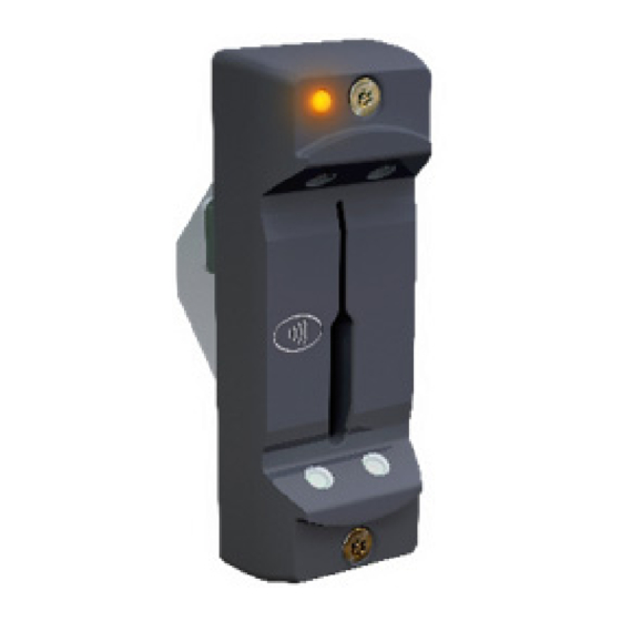
Page 53: Main Card Reader Tests
Post-Installation Testing Post-Installation Checks and Testing 4.2.5 Main Card Reader Tests ACS-1E and ACS-1EUL Install and Service Manual Ver 2... -
Page 54: Additional Test Procedures For The Mmr Card Reader
When planning to perform an MMR skim test, a device that operates as an NFC reader is required. Begin by turning on the ACS-1E or ACS-1EUL controller and performing MMR System Configuration. (Assistance from an administrator may be required.) Then, if the MMR reader is newly installed or replaced, perform the serial match operation by shorting the JP6 pins. - Page 55 Post-Installation Testing Post-Installation Checks and Testing Complete the following tests to confirm the normal operation of the MMR system. ACS-1E and ACS-1EUL Install and Service Manual Ver 2...
-
Page 56: Additional Feature Tests
Post-Installation Checks and Testing Post-Installation Testing 4.2.7 Additional Feature Tests ACS-1E and ACS-1EUL Install and Service Manual Ver 2... -
Page 57: Troubleshooting
• If yes, make sure the back of the exit button is wired correctly and confirm no physical damage to the exit button. Tone out the exit button to verify continuity. ACS-1E and ACS-1EUL Install and Service Manual Ver 2... - Page 58 Post-Installation Checks and Testing Troubleshooting This page intentionally left blank. ACS-1E and ACS-1EUL Install and Service Manual Ver 2...
Need help?
Do you have a question about the ACS-1E and is the answer not in the manual?
Questions and answers