Subscribe to Our Youtube Channel
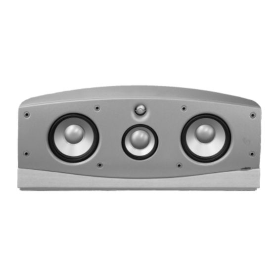
Summary of Contents for Infinity INTERMEZZO 3.5c
- Page 1 INTERMEZZO 3.5c Powered Center Channel Service Manual Infinity Systems, Inc 250 Crossways Park Dr. Woodbury, New York 11797 REV 2 3/2002...
-
Page 2: Table Of Contents
CONTROLS and CONNECTIONS ……………………….…………6 TEST SET UP AND PROCEDURE …………………………………8 SERVICE BULLETIN INF2002-3…………………….………………9 IM 3.5c ADJUST BIAS PROCEDURE………………………………10 EXPLODED VIEW of INTERMEZZO 3.5c …………………………11 EXPLODED VIEW of AMPLIFIER …………………………….……12 PACKAGING ……………………………………………………….…13 WIRING DIAGRAM/PASSIVE CROSSOVER NETWORK ………14 ELECTRICAL PARTS LIST ……………………………….…………15 INTEGRATED CIRCUIT DIAGRAMS ………………………………20... -
Page 3: Specifications
INTERMEZZO 3.5c Specifications Frequency Response: 80Hz - 20kHz (±1.5dB) 60Hz - 22kHz (±3dB) Recommended Amplifier Power Range 25-150 watts* Internal Amplifier Power 250 watts RMS (with 0.1% THD @ 100Hz) 2nd- and 3rd-Order Harmonic Distortion <1% (80Hz - 20kHz@95dB SPL) Sensitivity: 90dB (2.83V @ 1 meter) -
Page 4: Detailed Specifications
INTERMEZZO 3.5c Detailed Specifications... - Page 5 INTERMEZZO 3.5c Detailed Specifications (Cont.)
-
Page 6: Controls And Connections
INTERMEZZO 3.5c Controls and Connections... - Page 7 INTERMEZZO 3.5c Controls and Connections (Cont.)
-
Page 8: Test Set Up And Procedure
INTERMEZZO 3.5c Test Set Up and Procedure AC VOLT INTERMEZZ0 3.5c METER (10V) UNDER TEST SIGNAL GENERATOR SPEAKER AMPLIFIER OUTPUT FROM AMPLIFIER SYSTEM AURAL SWEEP TEST Equipment needed: Function/signal generator/sweep generator Integrated Amplifier Multimeter Speaker cables General Unit Function (UUT = Unit Under Test) 1. -
Page 9: Service Bulletin Inf2002-3
4. Locate the power supply section and R22 from the illustrations below. R22 can be checked in-circuit and should be 100k ohms ±5%. If it is any other value, or open, replace with Infinity part# RC0082. 5. Replace the amplifier, bottom cover, and test the loudspeaker. -
Page 10: Im 3.5C Adjust Bias Procedure
IM 3.5c ADJUST BIAS PROCEDURE (Mandatory when any output MOSFET transistors Q3,4,7,8 are replaced) 1. Amplifier should be unplugged and OFF. 2. Remove Amp assembly from cabinet, following the instructions on Page 9. All wires can remain connected unless they will prevent you from removing the amplifier or accessing potentiometers on the Linear board PCB in the following steps. -
Page 11: Exploded View Of Intermezzo 3.5C
INTERMEZZO 3.5c Exploded View of Intermezzo 3.5c NETWORK, 335269-001 SCREW (4), 8-32 x .5 MS PPH BLK 900201-008 MIDRANGE MIDRANGE TRANSDUCER CUP, TRANSDUCER 335226-001 SCREW (4), 335224-001 CABINET 6-32 x .5 MS PPH INTERMEZZO 3.5c, 900302-008 (NOT FOR SALE) REAR BASE... -
Page 12: Exploded View Of Amplifier
INTERMEZZO 3.5c Exploded View of Amplifier AC IEC SOCKET (JC0129) 1 FUSE HOLDER PANEL MT SEALED INPUT EQ PCB (FH0012) 1 FUSE, 3A 250V 1.25x.25 GLASS (FS0022) EMI FILTER PCB LINEAR PCB POWER SUPPLY 1 SWITCH, FRONT PANEL ROCKER TV5... -
Page 13: Packaging
INTERMEZZO 3.5c Packaging... -
Page 14: Wiring Diagram/Passive Crossover Network
INTERMEZZO 3.5c Wiring Diagram/Passive Crossover Schematic YEL + TWEETER YEL/BLK - 335225-002 AMPLIFIER 335710-001 MIDRANGE .250 TRANSDUCER 335224-001 .205 WHT/BLK WOOFER 335337-001 WOOFER 335337-001 GAIN CONTROL 335707-001 2.7uF 7.2uF 1.5ohm 7.5ohm 100v 100v .205 1.5ohm 7.5ohm 3.5uF 1.7mH 7.5ohm 100v 7.5ohm... -
Page 15: Electrical Parts List
INTERMEZZO 3.5c Electrical Parts List Part Description Designator... - Page 16 INTERMEZZO 3.5c Electrical Parts List (Cont.) Part Description Designator...
- Page 17 INTERMEZZO 3.5c Electrical Parts List (Cont.) Part Description Designator...
- Page 18 INTERMEZZO 3.5c Electrical Parts List (Cont.) Part Description Designator...
- Page 19 INTERMEZZO 3.5c Part Description Designator...
-
Page 20: Integrated Circuit Diagrams
INTERMEZZO 3.5c Integrated Circuit Diagrams... -
Page 21: Printed Circuit Board Diagrams
INTERMEZZO 3.5c Printed Circuit Board Diagrams... - Page 22 INTERMEZZO 3.5c Printed Circuit Board Diagrams (Cont.)
- Page 23 INTERMEZZO 3.5c Printed Circuit Board Diagrams (Cont.)
- Page 24 INTERMEZZO 3.5c Printed Circuit Board Diagrams (Cont.)
-
Page 25: Schematics
INTERMEZZO 3.5c Schematics... - Page 26 INTERMEZZO 3.5c Schematics (Cont.)
- Page 27 INTERMEZZO 3.5c Schematics (Cont.)
- Page 28 INTERMEZZO 3.5c Schematics (Cont.)


Need help?
Do you have a question about the INTERMEZZO 3.5c and is the answer not in the manual?
Questions and answers