Table of Contents
Advertisement
Reclosers
Form 6 Microprocessor-Based
Pole-Mount Recloser Control
Installation and Operation Instructions
For Type F6-P2A Control,
and Type F6-P2B Control,
above Serial Number 10,000
or beginning with CP57.
• F6-P2A applies to Form 6 control for
use with W, VS, and auxiliary-
powered NOVA reclosers.
• F6-P2B applies to control-powered
NOVA Form 6 control for use with
control-powered reclosers.
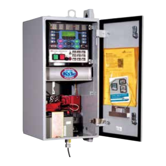
Figure 1.
Form 6 microprocessor-based pole-mount recloser control.
Contents
Safety Information ..................................................... 2
Product Information .................................................. 3
Introduction ............................................................ 3
ANSI Standards ...................................................... 3
Quality Standards ................................................... 3
Acceptance and Initial Inspection ........................... 3
Handling and Storage ............................................ 3
Control Power ........................................................ 3
Battery Replacement and Disposal ........................ 3
Operation Upon Loss of AC Power ........................ 4
Form 6 Recloser Control Description ...................... 5
Description ............................................................. 5
Theory of Operation ............................................... 5
Control Front Panel ................................................ 6
Control Features ..................................................... 11
Communications .................................................... 14
Control Information ................................................. 14
Control Back Panel ................................................ 14
Installation Procedure ............................................... 15
Initial Programming Prior to Installation ................... 15
Control / Recloser Compatibility ............................. 15
Duty Cycle Monitor ................................................. 16
Mounting the Control .............................................. 16
Locking the Control ................................................ 16
Control Cable ......................................................... 18
Grounding the Control ............................................ 18
Customer Connections for AC Power .................... 21
October 2012 • Supersedes 7/05
S280-70-3
Using Removable Inserts ........................................ 31
Accessories ............................................................... 32
Low Voltage Closing ............................................... 32
Internal Voltage Sensing .......................................... 32
Incoming Power Receptacles ................................. 32
Cable Locking Sleeves ........................................... 32
120 VAC GFI Duplex Outlet .................................... 32
BCT Terminal Blocks Accessory .............................. 41
Auxiliary Terminal Block Accessory .......................... 41
Cabinet Ordering Accessories ................................ 41
Discrete Interface Board Option Accessory ............ 42
Radio Mounting Accessory ..................................... 42
Communication Board Accessories ........................ 42
Testing ........................................................................ 45
Testing an Installed Control .................................... 45
Remove the Control from Service ........................... 46
Preliminary Testing with No AC Available ................ 46
Testing with Type MET Tester ................................. 46
Closing the Recloser During Testing ....................... 47
Battery Test and Charging Procedures ................... 50
Return the Control to Service ................................. 52
Recloser VTC Interface ............................................. 52
Control VTC Interface ............................................... 53
Additional Information ............................................... 54
Replacement Kits ................................................... 54
Factory-Authorized Service Centers ....................... 54
Factory Maintenance Classes ................................. 54
Service Information
1
Advertisement
Table of Contents

Subscribe to Our Youtube Channel
Related Manuals for Cooper Power Systems Form 6 Series


Summary of Contents for Cooper Power Systems Form 6 Series
-
Page 1: Table Of Contents
Reclosers Service Information Form 6 Microprocessor-Based S280-70-3 Pole-Mount Recloser Control Installation and Operation Instructions For Type F6-P2A Control, and Type F6-P2B Control, above Serial Number 10,000 or beginning with CP57. • F6-P2A applies to Form 6 control for use with W, VS, and auxiliary- powered NOVA reclosers. • F6-P2B applies to control-powered NOVA Form 6 control for use with control-powered reclosers. -
Page 2: Safety Information
Form 6 Microprocessor-Based Pole-mount Recloser Control Installation and Operation Instructions SAFETY FOR LIFE Cooper Power Systems products meet or exceed all applicable industry standards relating to product safety. We actively promote safe practices in the use and maintenance of our products through our service literature, instructional training programs, and the continuous efforts of all Cooper Power Systems employees involved in product design, manufacture, marketing, and service. -
Page 3: Product Information
Note: When shipped from the factory, the battery source is Cooper Power Systems sales representative. disconnected and its output plugs are taped to the cabinet. Connect the battery plugs into the mating ANSI Standards connectors to complete the battery circuit. -
Page 4: Operation Upon Loss Of Ac Power
Form 6 Microprocessor-Based Pole-mount Recloser Control Installation and Operation Instructions Operation Upon Loss of AC Power The control is equipped with either an 8 Amp-Hour or 13 Amp-Hour 24 VDC lead acid battery for operation upon loss of AC power. The control maintains full operation from the battery for a period of time dependent upon the battery size: •... -
Page 5: Form 6 Recloser Control Description
S280-70-3 FORM 6 RECLOSER CONTROL DESCRIPTION Description The control can be configured, by the factory or by the user, for a wide variety of applications. If user requirements The Form 6 pole-mount microprocessor-based recloser change, the control functions can be modified to meet the control includes extensive system protection functionality, new requirements. -
Page 6: Control Front Panel
Form 6 Microprocessor-Based Pole-mount Recloser Control Installation and Operation Instructions sequence after a preset time delay. If the fault is permanent, The control includes a Power Save feature that will turn off the control performs its complete programmed sequence the backlit LCD display and all LEDs (except Hot Line Tag) of reclose commands and locks out with the recloser open. - Page 7 S280-70-3 Programming Panel LCD Display The LCD Display is a backlit 4-line, 20-character display The Programming panel has the following sections: that provides extensive distribution system, recloser, and One-Touch Analysis Keys control status information using a minimum of eight navigation keypads (Figure 5). There are eight analysis keys (Figure 5) that allow one- button access to a variety of control and monitoring func- Note:...
- Page 8 Form 6 Microprocessor-Based Pole-mount Recloser Control Installation and Operation Instructions Status Indicator LEDs RECLOSER CLOSED: The red LED indicates the recloser is in the closed position. The status indicator LEDs (Figure 6) in the Programming section of the Operator Panel give instant information on Note: There are several conditions that will cause the alternate blinking of the CONTROL LOCKOUT, RECLOSER OPEN,...
- Page 9 S280-70-3 Operating Panel CLOSE CIRCUIT DISABLE Close Circuit Disable (Figure 7) is a removable fuse that, RS-232 Configuration Data Port when removed from the front operating panel, disables the The RS-232 connector (shown in Figure 4) on the front close circuit from the control to the recloser. Removing the operating panel allows direct connection to a personal fuse from the control disables all electrical closing of the computer without any special cables or connectors.
- Page 10 Form 6 Microprocessor-Based Pole-mount Recloser Control Installation and Operation Instructions One-Touch Function Keys SUPERVISORY OFF Quick access to frequently operated Form 6 control fea- When the SUPERVISORY OFF red indicator is illuminated, tures is provided with nine function key pushbuttons on the supervisory commands are blocked.
-
Page 11: Control Features
S280-70-3 Control Features Sequence Coordination Sequence Coordination eliminates nuisance tripping The Form 6 pole-mount recloser control offers numerous through trip coordination. It allows the control to step standard features and accessories that allow the user the through selected operations in the operating sequence utmost flexibility applying the recloser control. - Page 12 Form 6 Microprocessor-Based Pole-mount Recloser Control Installation and Operation Instructions Metering The control also provides a minimum of three configurable input control contacts. Each control contact is configurable The control provides instantaneous and/or demand using a graphical interface software. Contacts accept a metering with programmable integration intervals for the whetting voltage range of 12–250 VDC, 120/240 VAC.
- Page 13 S280-70-3 1 T. Takagi, Y. Yamakoshi, J. Baba, K. Uemura, T. Sakaguchi, "A New Removable Inserts Algorithm of an Accurate Fault Location for EHV/UHV Transmission Lines: Removable inserts are included with the control design for Part I - Fourier Transformation Method", IEEE Trans. on PAS, Vol. PAS-100, No.
-
Page 14: Communications
Form 6 Microprocessor-Based Pole-mount Recloser Control Installation and Operation Instructions Communications Ethernet configuration is accomplished via ProView interface software. Refer to Service Information S280-70-4 Communication Ports (ProView 4.X.X) or S280-70-21 (ProView 5.X.X) Form 6 Programming Guide , Section 4: Schemes, Communicating The Form 6 control has two back panel communication with the Form 6 Control, for Ethernet Configuration ports and a front panel configuration data port. -
Page 15: Installation Procedure
S280-70-3 INSTALLATION PROCEDURE Initial Programming Control / Recloser Compatibility Prior to Installation The Form 6 pole-mount recloser control is adaptable to the following Kyle reclosers: CAUTION: Equipment misoperation. Do not WE*, WVE27, WVE38X, VWE, VWVE27, VWVE38X, RVE, connect this control to an energized recloser until VSA12, VSA16, VSA20, VSA12B, VSA20A, VS012, VS016, all control settings have been properly programmed and NOVA15**, NOVA27** and NOVA38**. -
Page 16: Duty Cycle Monitor
For reclosers shipped prior to June 1989 and not listed Note: Mount the Form 6 pole-mount recloser control in a below, please contact your Cooper Power Systems convenient, accessible location. Mounting dimensions are representative with the recloser type and serial number provided in Figure 10. - Page 17 S280-70-3 SHACKLE DIAMETER .177-295" SHACKLE DIAMETER .295-.394" Note: DO NOT use a smaller shackle (.177- .295) in the larger diameter hole as it will NOT LOCK the cabinet. (1.25) 16 (.63) Dia. (12.25) Mounting Holes (2) RS-232 Lifting CONTROL OK A PHASE FAULT ALARM A PHASE VOLTAGE...
-
Page 18: Control Cable
Form 6 Microprocessor-Based Pole-mount Recloser Control Installation and Operation Instructions Control Cable Grounding the Control WARNING: Hazardous voltage. Recloser and WARNING: Hazardous voltage. Recloser and control must be solidly grounded. Follow all control must be solidly grounded. Follow all approved procedures and safety practices when locally approved procedures and safety practices when grounding this equipment. - Page 19 S280-70-3 Grounding with a Local Supply Voltage Transformer; 4-Wire Multi-Grounded Installation of a Form 6 pole-mount recloser control with 4-Wire Multi-Grounded Systems a local supply voltage transformer must include the following: IMPORTANT: In pole-mounted applications, a ground connection must be made between the recloser, •...
- Page 20 Form 6 Microprocessor-Based Pole-mount Recloser Control Installation and Operation Instructions Grounding with a Remote Supply Voltage Transformer; 4-Wire Multi-Grounded IMPORTANT: In pole-mounted applications, a ground Installation of a Form 6 pole-mount recloser control with a connection must be made between the recloser, remote supply voltage transformer must include the transformer, recloser control, and SCADA equipment for following:...
-
Page 21: Customer Connections For Ac Power
S280-70-3 Customer Connections for AC Power CAUTION: Equipment misoperation. Verify that the 120/240 VAC selector switch is correctly set DANGER: Hazardous voltage. Do not connect for incoming voltage. Failure to comply may cause potential transformer low-voltage secondaries to misoperation (unintentional operation) of the control the control through cables or other wiring until the unit is and/or equipment damage resulting in personal injury. - Page 22 Form 6 Microprocessor-Based Pole-mount Recloser Control Installation and Operation Instructions Voltage Sensing Connections Source Load V (1-2) V(3-4) V(5-6) BØ Factory Wiring for Wye Connection Note: Terminal Block positions TB7-3 and TB7-4 are factory-jumpered together. Terminal Block positions TB7-5 and TB7-6 are factory-jumpered together.
- Page 23 S280-70-3 Voltage Sensing Connections Load Source V (1-2) V(3-4) V(5-6) AØ User-Supplied Disconnect Switch AØ Terminal Block positions TB7-3 and TB7-4 Note: are factory-jumpered together. 120/240 (L2) Terminal Block positions TB7-5 and TB7-6 120 (L1) are factory-jumpered together. Power Connections Figure 16.
- Page 24 Form 6 Microprocessor-Based Pole-mount Recloser Control Installation and Operation Instructions CØ Voltage Sensing Connections Load Source V(3-4) V(5-6) V (1-2) BØ AØ Terminal Block positions TB8-1 and TB8-6 are Note: User-Supplied Disconnect factory-jumpered together for Delta connection Switches only. DANGER: Hazardous voltage. Do not connect potential transformer low-voltage secondaries to Terminal Block positions TB8-2 and TB8-3 are the control through cables or other wiring until the unit is...
- Page 25 S280-70-3 Standard Default Supervisory Input TABLE 4 Control and Output Status Contacts Operating Current Requirements for Standard and Optional Supervisory Inputs Standard customer connections TB1 and accessory customer connections are TB3 and TB4. Refer to Figures Nominal Minimum 20 and 21 and Tables 4, 5, and 6. The Idea Workbench Input Voltage Current Operating Time...
- Page 26 Form 6 Microprocessor-Based Pole-mount Recloser Control Installation and Operation Instructions IMPORTANT Shielding and Surge Protection of Supervisory Cables All supervisory operation and control monitor leads must be protected within shielded cables. Refer to Figure NOTICE: External leads must be shielded and the shield must be grounded at both ends.
- Page 27 S280-70-3 Figure 21. Form 6 pole-mount recloser control Discrete Interface Board accessory default supervisory input control and out- put status contacts.
- Page 28 Form 6 Microprocessor-Based Pole-mount Recloser Control Installation and Operation Instructions FORM 6 POLE MOUNT RECLOSER CONTROL SHIELD Customer Wiring 28 VDC Whetting Voltage Terminals Factory-Supplied 28 VDC Whetting Voltage — Customer Wiring REMOTE Supervisory Trip and Lockout Supervisory Close Remote Trip and Lockout Recloser...
- Page 29 S280-70-3 Rear Panel RS-232 Communication Port IRIG-B Time RS-232 Serial Pin Assignments Communication Port Sync Connector Tables 7 indicates the pin assignments for the rear panel RS-232 communication port (Figure 23). Refer to Figure 24 for pin identification. Refer to Protocols for additional information.
-
Page 30: Before Placing Control And Recloser Into Service
Form 6 Microprocessor-Based Pole-mount Recloser Control Installation and Operation Instructions Before Placing the Control and the 8. Control battery connected and tested for proper operation. Recloser into Service Note: The battery test is blocked for 30 seconds upon power-up of the control. CAUTION: Equipment misoperation. -
Page 31: Using Removable Inserts
S280-70-3 Using Removable Inserts 4. Use tweezers to gently pull out the removable insert. Note: The insert will slide out of the right side of the CAUTION: Control damage. De-energize both AC and operating panel (Figure 26). DC power prior to removing or installing any internal The insert will slide out of the top of the programming Note: connections or circuit boards in the control. -
Page 32: Accessories
Catalog Note: The internal voltage sensing cable Description Number (KA97ME) is ordered with the recloser. If a Internal Voltage Sensing input receptacle, 4-pin ........ KME6-3799-1S replacement cable is required, contact your Cooper Power Systems representative. - Page 33 S280-70-3 DANGER: Hazardous voltage. Do not connect potential transformer low-voltage secondaries to the control through cables or other wiring until the unit is 120/240 VAC installed in the field. Transformer high-voltage primary Power Supply windings will become live when 120V AC is applied to the control from an alternate source if the transformer secondary is connected.
- Page 34 Form 6 Microprocessor-Based Pole-mount Recloser Control Installation and Operation Instructions DANGER: Hazardous voltage. Do not connect potential transformer low-voltage secondaries to the control through cables or other wiring until the unit is installed in the field. Transformer high-voltage primary 120/240 VAC windings will become live when 120V AC is applied to Power Supply the control from an alternate source if the transformer...
- Page 35 S280-70-3 DANGER: Hazardous voltage. Do not connect potential transformer low-voltage secondaries to the control through cables or other wiring until the unit is installed in the field. Transformer high-voltage primary windings will become live when 120V AC is applied to the control from an alternate source if the transformer secondary is connected.
- Page 36 Form 6 Microprocessor-Based Pole Mount Recloser Control Installation and Operation Instructions DANGER: Hazardous voltage. Do not connect potential transformer low-voltage secondaries to the control through cables or other wiring until the unit is installed in the field. TB10 120/240 VAC Transformer high-voltage primary windings will Power Supply become live when 120V AC is applied to the con-...
- Page 37 S280-70-3 DANGER: Hazardous voltage. Do not connect potential transformer low-voltage secondaries to the control through cables or other wiring until the TB10 120/240 VAC unit is installed in the field. Transformer high- Power Supply voltage primary windings will become live when 120V AC is applied to the control from an alter- nate source if the transformer secondary is con- Connections...
- Page 38 Form 6 Microprocessor-Based Pole Mount Recloser Control Installation and Operation Instructions Voltage Sensing Connections Load Source V(3-4) V(5-6) V (1-2) White BØ Black Factory Wiring for Wye Connection Note: Terminal Block positions TB7-3 and TB7-4 are factory-jumpered together. Terminal Block positions TB7-5 and TB7-6 are factory-jumpered together.
- Page 39 S280-70-3 Voltage Sensing Connections Load Source V(3-4) V(5-6) V (1-2) White BØ Black Factory Wiring for Wye Connection Note: Terminal Block positions TB7-3 and TB7-4 are factory-jumpered together. Terminal Block positions TB7-5 and TB7-6 are factory-jumpered together. 120/240 (L2) 120 (L1) Power Connections Braid Input...
- Page 40 Form 6 Microprocessor-Based Pole Mount Recloser Control Installation and Operation Instructions Voltage Sensing Connections Load Source V (1-2) V(3-4) V(5-6) White BØ Black Factory Wiring for Wye Connection Note: Terminal Block positions TB7-3 and TB7-4 are factory-jumpered together. Terminal Block positions TB7-5 and TB7-6 are factory-jumpered together.
-
Page 41: Bct Terminal Blocks Accessory
S280-70-3 BCT Terminal Blocks Accessory TABLE 10 Terminal Blocks The BCT Terminal Blocks (Figure 31) attach to the back of Description Catalog Number the control and provide a connection point for external 600:5 or 1200:5 multi-ratio bushing current transformers. BCT shorting-type terminal block for (LOAD) bushings 2, 4, 6 . -
Page 42: Discrete Interface Board Option Accessory
Refer to Table 11. CO7 CO8 CO9 CO10 CO11CO12 CI4 CI5 CI6 CI7 CI8 CI9 CI10 CI11 CO5 CO6 Contact your Cooper Power Systems representative for any additional voltage requirements. – 28 VDC WHETTING VOLTAGE... - Page 43 2000m with 62.5/125µm multi-mode fiber. Consult remote terminal unit (RTU), wireless, telephone modem, your Cooper Power Systems representative for availability Ethernet network, or other communication devices. The of long haul solutions. Link communication speed is con-...
- Page 44 Form 6 Microprocessor-Based Pole-mount Recloser Control Installation and Operation Instructions Standard (No Communication Option) RS-485 Communication Serial Fiber RS-485 C NON-ECHO IRIG-B IRIG-B IRIG-B Default J4 – ETHERNET – J3 J4 – ETHERNET – J3 J4 – ETHERNET – J3 J4 –...
-
Page 45: Testing
S280-70-3 TESTING 3. Test battery operation as follows: CAUTION: Equipment misoperation. Do not Note: The battery test is blocked for 30 seconds upon connect this control to an energized recloser until power up of the control. all control settings have been properly programmed and Note: AC power can be either connected or disconnected verified. -
Page 46: Remove The Control From Service
Form 6 Microprocessor-Based Pole-mount Recloser Control Installation and Operation Instructions Remove the Control from Service Preliminary Testing with No AC Available IMPORTANT: Disconnect switches for AC sensing and power connections are necessary to isolate the Form 6 If the Form 6 control is not in service and requires control for testing and servicing. -
Page 47: Closing The Recloser During Testing
S280-70-3 The MET Tester is completely self-contained, capable of WARNING: Hazardous voltage. Interconnect performing all required checks and tests from a simple source leads X and Y and ground solidly to the verification of operation to a complete verification of all recloser tank (Figure 46). - Page 48 Form 6 Microprocessor-Based Pole-mount Recloser Control Installation and Operation Instructions • Variable Autotransformer T1, 230 Volts, 20 Amps. Variable • Low-Voltage transformer T2 to simulate fault conditions. 115Vac Autotransformer (10 Amp) Ratio and size will depend upon the maximum current 600:5 Recloser to be used.
- Page 49 S280-70-3 Electrical Closing – Motor-Operated Manual Closing – Solenoid-Operated Low-Voltage Closing Solenoid / Auxiliary- Reclosers Powered NOVA Reclosers WARNING: Explosion hazard. Excessive Contact Arcing. Do not use the manual closing WARNING: Hazardous voltage. Solidly ground tool to close an oil-insulated energized recloser. Closing all equipment.
-
Page 50: Battery Test And Charging Procedures
Form 6 Microprocessor-Based Pole-mount Recloser Control Installation and Operation Instructions Battery Test and Charging 4. Press the F4 button to test the battery. The battery test results will display in the battery metering menu. Procedures Note: Voltage should be between 25–31 VDC with the Test Procedure for Installed Battery higher voltage at colder temperatures. - Page 51 S280-70-3 Battery Charging The charger senses when the battery voltage reaches 2.27 volts per cell, then the charge rate reduces to maintain a If it is not possible to charge the battery with the control’s trickle charge. built-in charger, a KME5-60-1 (120 VAC) portable bench The yellow LED flickers to indicate the battery has reached type battery charger kit is available, which includes the a full charge.
-
Page 52: Return The Control To Service
Form 6 Microprocessor-Based Pole-mount Recloser Control Installation and Operation Instructions RECLOSER VTC INTERFACE Return the Control to Service CAUTION: Equipment misoperation. Do not Control-Powered Type NOVA reclosers with serial numbers connect this control to an energized recloser until 100,000 and above, as listed in Table 15, require a VTC- all control settings have been properly programmed and ready control. -
Page 53: Control Vtc Interface
S280-70-3 CONTROL VTC INTERFACE All Form 5 and Form 6 recloser controls that have the VTC control retrofit kits are available for Form 5 or Form 6 control-powered interface with serial numbers over those recloser controls with serial numbers below those shown in shown in Table 16 are VTC-ready. -
Page 54: Additional Information
Systems representative for additional information and order procedures. Factory-Authorized Service Centers Factory-authorized service centers are located throughout the continental United States to provide maintenance, repair and testing services for Cooper Power Systems controls and reclosers. For further information, contact your Cooper Power Systems representative. - Page 55 S280-70-3...
- Page 56 Form 6 Microprocessor-Based Pole-mount Recloser Control Installation and Operation Instructions ©2012 Cooper Industries. All Rights Reserved. All Cooper logos, Cooper Power Systems, Kyle, ProView, Idea Workbench, Communications Workbench, and TCC Editor are trade- marks of Cooper Industries in the U.S. and other countries. You are not permitted to use Cooper trademarks without the prior written consent of Cooper Industries.
Need help?
Do you have a question about the Form 6 Series and is the answer not in the manual?
Questions and answers