Table of Contents
Advertisement
Reclosers
Type ME Electronic Recloser Control,
Form 3 and 3A
Maintenance Instructions - Basic
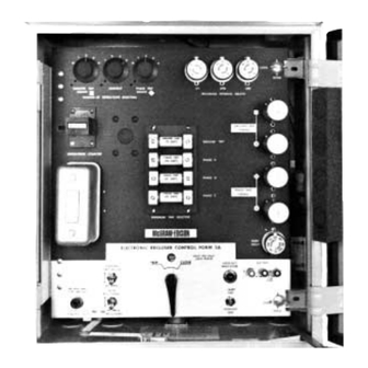
Figure 1.
®
Kyle
Type ME electronic recloser control
CONTENTS
Safety Information . . . . . . . . . . . . . . . . . . . . . . . . . . . . 2
Introduction . . . . . . . . . . . . . . . . . . . . . . . . . . . . . . . . . 3
. . . . . . . . . . . . . . . . . . . . . . . . . . . . . . . . . 3
Operation . . . . . . . . . . . . . . . . . . . . . . . . . . . . . . . . . . . 5
Periodic Field Inspection and Maintenance . . . . . . . 6
Servicing . . . . . . . . . . . . . . . . . . . . . . . . . . . . . . . . . . . 8
Circuit Logic . . . . . . . . . . . . . . . . . . . . . . . . . . . . . . . 8
Plug-In Circuit Boards Function . . . . . . . . . . . . . . . .10
Battery Charging Board . . . . . . . . . . . . . . . . . . . .10
Phase Trip No. 1 Board . . . . . . . . . . . . . . . . . . . .11
Phase Trip No. 2 Board . . . . . . . . . . . . . . . . . . . .11
Ground Trip No. 1 and No. 2 Boards . . . . . . . . . .11
Output Board . . . . . . . . . . . . . . . . . . . . . . . . . . . .12
Diode Board . . . . . . . . . . . . . . . . . . . . . . . . . . . . .12
Recloser-Reset Board . . . . . . . . . . . . . . . . . . . . .12
Closing Coil Control Fuse . . . . . . . . . . . . . . . . . . . . .12
Form 3 and Form 3A Electronic Controls . . . . . . . . .12
Troubleshooting and Testing . . . . . . . . . . . . . . . . . . .13
Detailed Circuit Checks . . . . . . . . . . . . . . . . . . . . . . .14
Input Circuits . . . . . . . . . . . . . . . . . . . . . . . . . . . .17
Internal dc Load Current Signal . . . . . . . . . . . . . .
These instructions do not claim to cover all details or variations in the equipment, procedure, or process described, nor to provide direction for
meeting every possible contingency during installation, operation, or maintenance. When additional information is desired to satisfy a problem not
covered sufficiently for the user's purpose, please contact your Cooper Power Systems sales engineer.
April 2002
Supersedes 12/88
Internal Minimum Trip Signal .....................................19
Time-Current Characteristic Curves (TCC) ................20
Control-Recloser operation ........................................22
Major Control Damage ...............................................29
Battery Charging ........................................................31
Mechanical and Electrical Hardware ..........................35
Battery Maintenance ...........................................................35
Battery Specifications ......................................................35
Maintaining Battery Charge .............................................35
Field Testing a Battery .....................................................35
Shop Testing a Battery .....................................................36
Appendix I ...........................................................................37
Test Sheet ........................................................................37
Appendix II ..........................................................................38
List of Electronic Recloser Maintenance Manuals ...........38
Appendix III .........................................................................38
List of Electronic Control Accessory Manuals ..................38
Appendix IV .........................................................................38
Service Parts List .............................................................38
Appendix V ..........................................................................41
Form 2 Connection Diagram ............................................42
Form 3 Connection Diagram ............................................44
Form 3A Connection Diagram .........................................48
18
Service Information
S280-75-2
88936KMA
1
Advertisement
Table of Contents

Related Manuals for Cooper Power Systems Kyle Type ME Series


Summary of Contents for Cooper Power Systems Kyle Type ME Series
-
Page 1: Table Of Contents
These instructions do not claim to cover all details or variations in the equipment, procedure, or process described, nor to provide direction for meeting every possible contingency during installation, operation, or maintenance. When additional information is desired to satisfy a problem not covered sufficiently for the user’s purpose, please contact your Cooper Power Systems sales engineer. April 2002... -
Page 2: Safety Information
FOR LIFE FOR LIFE Cooper Power Systems products meet or exceed all applicable industry standards relating to product safety. We actively promote safe practices in the use and maintenance of our products through our service literature, instructional training programs, and the continuous efforts of all Cooper Power Systems employees involved in product design, manufacture, marketing, and service. -
Page 3: Introduction
S280-75-2 perienced service technicians, are held at the factory’s in-house INTRODUCTION training facility. For additional information, contact your sales engi- Service Information S28O-75-2 covers basic maintenance neer. instructions for the Type ME electronic control. The manual includes a general description of the control, its operating principles and instructions for periodic inspection and testing. - Page 4 Type ME Electronic Recloser Control of the front panel contains the plug-in components and setting current, exceeds its programmed minimum-trip value, the knobs for programming automatic recloser operation. The electronic control initiates the programmed sequence of switches and indicators used for manual operation and service recloser tripping and reclosing operations.
-
Page 5: Operation
S280-75-2 • OPERATION Home Position—Position of sequence relay immediately after a Since the understanding of the terminology and the operat- reset operation of the control. Reset operation can be either ing sequences of an electronically controlled recloser is manual, by moving the Manual Control Switch to “CLOSE”, or important to the rest of this maintenance manual, examples automatic, after a temporary fault. -
Page 6: Periodic Field Inspection And Maintenance
Type ME Electronic Recloser Control A functional block diagram of the control operation is shown PERlODIC FIELD INSPECTlON in Figure 6. Line current conditions are continuously monitored AND MAINTENANCE by the three bushing-type current transformers in the recloser. Periodic inspection of the ME control should include these proce- output from these transformers is fed to the trip network in the dures: control, which includes: the minimum-trip resistors, isolation... - Page 7 S280-75-2 88939KMA Figure 7. View of a Form 3A tie board (back if front panel. Notations in parenthesis after callout refer to the circuit points on the tie board dia- gram illustrated in Figure 57. 7. Check battery voltage. Three battery test terminals in the to the “Detailed Circuit check—Battery Charging”...
-
Page 8: Servicing
Type ME Electronic Recloser Control Figure 8. Detailed block diagram of Type ME control in lockout position. Letters in circles (A,B, etc.) refer to control cable receptacle connec- tion pins and to test points referred to in the "Troubleshooting and Testing" section. SERVICING 9. - Page 9 S280-75-2 Figure 9. Diagram of Form 3A tie board showing plug-in circuit board location. Form 3 tie boards are similar (see Figure 18), except some of the terminals are missing or in a slightly different location. From this point, phase- and ground-trip signals are very If the load current conditions are in the fault region, the mini- similar, and only phase signals will be described.
-
Page 10: Plug-In Circuit Boards Function
Type ME Electronic Recloser Control After the timing plugs have completed their cycle, the output Plug-in Circuit Boards - Function board is triggered. The output board applies a 24-Vdc signal to The ME control contains a total of eight plug-in circuit boards on the recloser trip coil, the control counter, and the control which are assembled the bulk of its operating circuits. -
Page 11: Phase Trip No. 1 Board
S280-75-2 PHASE-TRIP NO. 2 BOARD The phase-trip No. 2 board (Figure 12) carries the remaining cir- cuits for minimum-trip and the wave-shaping circuits for the timing plugs. There are two tabs on the phase-trip No. 2 board for the Form 3 and 3A control. one tab is labeled minimum-trip (MIN. TRIP)* and is battery plus for normal line currents and switches to battery minus for fault currents;... -
Page 12: Output Board
Type ME Electronic Recloser Control OUTPUT BOARD The output board (Figure 15) of the control has another do amplifier which senses the charge on the timing plugs and at the proper time gates the tripping SCR. This board also carries the diodes and resistors which make up the various reference voltages for the control. -
Page 13: Troubleshooting And Testing
S280-75-2 TABLE 1 TROUBLESHOOTING AND TESTING Pre-Check A number of relatively simple circuit tests can be made on the ME electronic control. These tests will indicate whether Trouble Check major circuits are operating properly or not, but they will not necessarily isolate the faulty component within the circuit. -
Page 14: Detailed Circuit Checks
Type ME Electronic Recloser Control 82047KMA Figure 19. Form 3 electronic control tie board and control back panel.The test points listed above will be covered in detail in the "Detailed Circuit Check" section of this manual. Pre-Check When troubleshooting a control reported to have failed or to CAUTION: Be sure that test equipment leads have not worked properly, always check for simple problems have insulated clips to prevent short circuiting adja-... - Page 15 S280-75-2 Figure 20. 88948KMA Form 3A electronic control tie board.The test points listed above will be covered in detail in the "Detailed Circuit Check" section of this manual. • If a circuit board failure is suspected, always check or A primary diode failure on the diode board can cause sec- change the diode board first because: ondary failures on the output board or reclose set board.
- Page 16 Type ME Electronic Recloser Control Figure 21. 88939KMA Form 3A electronic control back panel.The test points listed above will be covered in detail in the "Detailed Circuit Check" section of this manual.
-
Page 17: Input Circuits
S280-75-2 INPUT CIRCUITS WARNING: High voltage. Contact with high volt- age will cause serious personal injury or death. Follow all locally approved safety procedures when working around high voltage lines and equipment. To check input signals to the control, measure the voltage across the minimum-trip resistors and matching transformer secondaries as follows: 1. -
Page 18: Internal Dc Load Current Signal
Type ME Electronic Recloser Control Figure 24. 88950KMA Measuring voltage across matching transformers (Table 2) (control panel open, middle left hand side of control). INTERNAL dc-LOAD-CURRENT SIGNAL To check the dc-load-current output signal, measure the volt- age at tie board test points listed in Table 3 at 100% minimum- trip current. -
Page 19: Internal Minimum Trip Signal
S280-75-2 INTERNAL MINIMUM TRIP SIGNAL To check the minimum-trip signal, measure the voltage at tie board test points listed in Table 4. Failures to get these signals are most likely due to troubles on the phase-trip No. 2 or ground-trip No. 2 circuit boards or possi- bly with the phase-trip No.1 or ground-trip No.1 boards. -
Page 20: Time-Current Characteristic Curves (Tcc)
Type ME Electronic Recloser Control TIME CURRENT CHARACTERISTIC CURVES (TCC) NOTE: Since some volt meter burdens will change control calibration, this test will only verify TCC plug operation. To check the charging of the phase-or-ground-TCC plug, measure the voltage drop at the tie board and the TCC socket pin test points listed in Table 5. - Page 21 S280-75-2 Figure 32. 82040KMA Form 3 test points for TCC operation (Table 5). For relationships of terminal/pin location on the tie board and rear of front panel, see Figures 18 and 19. Figure 33. 88948KMA Form 3 test points for TCC operation (Table 5). For relationships of terminal/pin location on the tie board and rear of front panel, see Figures 20 and 21.
-
Page 22: Control-Recloser Operation
Type ME Electronic Recloser Control CONTROL-RECLOSER OPERATION electronic control are shown in Figures 34 and 35. For detailed information on electronic recloser/control operational circuits, con- To provide a better understanding of the control operational cir- sult the maintenance manual for your recloser (see Appendix 11). cuit checks and the relationship between the recloser circuits and the control output, typical recloser connections to the ME Figure 34. - Page 23 S280-75-2 To check voltage changes during typical recloser-trip operations, measure voltage at test points listed in Table 6. Failure to get voltage readings indicated usually indicates problems in the recloser. Consult the recloser maintenance manual for testing and service information (see Appendix 11). TABLE 6 Test Points for Trip Operating Circuit (Figures 36, 37, and 38)
- Page 24 Type ME Electronic Recloser Control To check voltage changes during closing from lockout, tripping and reclosing, measure voltages at test points listed in Table 7. Failure to get voltage readings indicated usually indicates prob- lems in the recloser. Consult the recloser maintenance manual for testing and service information (see Appendix 11).
- Page 25 S280-75-2 Figure 40. 82040KMA Form 3 test points for closing, tripping and reclosing operation (Table 7). For relationship of terminal test points, see Figures 2, 18 and 19. Figure 41. 88948KMA Form 3 test points for closing, tripping and reclosing opeation (Table 7). For relationship of terminal test points, see Figures 2, 18 and 19.
- Page 26 Type ME Electronic Recloser Control To check voltage changes during trip and reset opera- TABLE 8 tions, measure voltage at test points listed in Table 8. Test Points for Trip and Reset Circuit Failure to get voltage readings indicated usually indicates (Figures 42, 43 and 44).
- Page 27 S280-75-2 Figure 43. Form 3 test points for trip-reset operation (Table 8). For relationship of terminal test points, see Figures 2, 18 and 19.
- Page 28 Type ME Electronic Recloser Control Figure 44. Form 3A test points for trip-reset operation (Table 8). For relationship of terminal test points, see Figures 2, 20, and 21.
-
Page 29: Major Control Damage
S280-75-2 MAJOR CONTROL DAMAGE TABLE 9 To verify the condition of the Form 3 and 3A tie board in the Form 3 Tie Board Continuity Checks (Figure 45) event of major control damage, check the continuity of common tie board terminals listed in Table 9 (Form 3) and Table 10 (Form 3A). - Page 30 Type ME Electronic Recloser Control TABLE 10 Form 3A Tie Board Continuity Checks (Figure 46) Continuity from Continuity from Terminals "A+" To Terminals "N-1" To* Lamp Counter 1 * For controls with capacitor backup trip accessory (KA1119ME or KA1122ME, check continuity from diode point shown on Figure 47. Figure 46.
-
Page 31: Battery Charging
S280-75-2 BATTERY CHARGING temperature regulated charging board (MEA 1172), See Figure To check the battery charging operation: 48). A typical charging rate will be about 27 mA, at normal room 1. Make sure control is in home (reset) position by moving temperature. - Page 32 Type ME Electronic Recloser Control Figure 49. Block diagram of test points for battery-charging circuitry. See Figures 50 and 51 and Tale 12 for specific testing points and values.
- Page 33 S280-75-2 TABLE 12 Battery-Charging Circuitry Checks (Figures 49, 50 and 51) Voltage Reading (Vac) Test Points Location Form 3 Form 3A Form 3A If Voltage Reading Is Fixed Rate Temperature Not Obtained, Check: Charger Regulated Charger • Incoming - Fused switch 120/240 Low voltage supply •...
- Page 34 Type ME Electronic Recloser Control Figure 51. Form 3A test points for battery-charging circuitry (Table 12).
-
Page 35: Mechanical And Electrical Hardware
S280-75-2 MECHANICAL AND ELECTRICAL HARDWARE CAUTION: Do not short battery positive to the All mechanical and electrical hardware components (selector control cabinet (or other ground). If shorted on a switches, toggle switches, manual switch, operations counter, Form 3 control the control will be permanently damaged, trip sockets, phase sockets, resistor brackets, fuse receptacle, etc.) can be visually or electrically checked. -
Page 36: Shop Testing A Battery
Type ME Electronic Recloser Control Figure 53. Typical voltage versus temperature characteristics of nickel-cadmium battery. has this built in) across the battery for approximately 2-3 sec- Shop Testing a Battery onds. The voltage must not drop more than 3-volts below the Before testing, the top and bottom covers of the battery should open circuit voltage for temperatures above 20-degrees F. -
Page 37: Test Sheet
S280-75-2 APPENDIX I Test Sheet NOTE: The following sample test sheet is a convenient method to systematically test the ME electronic control and then return it to its original pro- gramming condition TEST RECORD SHEET FOR TYPE ME ELECTRONIC CONTROL DATE CIRCUIT NO. -
Page 38: List Of Electronic Recloser Maintenance Manuals
Type ME Electronic Recloser Control APPENDIX II APPENDIX IV Maintenance Manuals ME Contol Parts NOTE: For reference to Control parts and components, refer to Figures 2, TABLE 13 7, 55, 56 and 57. For current prices, see the latest edition of the Parts Electronic Recloser Maintenance Manuals Price List. - Page 39 S280-75-2 TABLE 16 Type ME Control Circuit Boards and Control Cables Form 2 (Above S/N 1900), Form 3 (Above S/N 4000, Form 3A (Above S/N 26000) Catalog No. Description Catalog No. Description KA1ME7 Control Cable, 7 Ft. All Reclosers KA381MES Reclose and Reset Circuit Board for Form 3 KA1MEXX Longer Control Cable: 8 Thru 80 Ft.
- Page 40 Type ME Electronic Recloser Control TABLE 17 Type ME Control Replacement Parts Acessories Form 2 (Above S/N 1900), Form 3 (Above S/N 4000), Form 3A (Above S/N 26000) (continued) Catalog No. Description Catalog No. Description KA716ME Reclosing Fuse Replacement Kit KA1037ME6S Instantaneous Trip—Phase and Ground.
-
Page 41: Appendix V
S280-75-2 APPENDIX V Schematic diagrams Form 2 Connections ........... .pages 42-43 Form 3 Connections (below S/N 5500) . -
Page 42: Form 2 Connection Diagram
Type ME Electronic Recloser Control Form 2 Connections Figure 54. Form 2 connection diagram (below S/N 1900). Since late Form 2 and early Form 3 controls share common circuits and design, this connection diagram is given for reference. - Page 43 S280-75-2 Form 2 Connections - continued Figure 54 - continued.
-
Page 44: Form 3 Connection Diagram
Type ME Electronic Recloser Control Form 3 Connections Figure 55. Form 3 connection diagram (below S/N 5500). - Page 45 S280-75-2 Form 3 Connections - continued Figure 55 - continued.
-
Page 46: Form 3 Connections (S/N 5500-25999)
Type ME Electronic Recloser Control Form 3 Connections Figure 56. Form 3 connection diagram (S/N 5500 to 25999). - Page 47 S280-75-2 Form 3 Connections - continued Figure 56 - continued.
-
Page 48: Form 3A Connection Diagram
Type ME Electronic Recloser Control Form 3A Connections Figure 57. Form 3A connection diagram. - Page 49 S280-75-2 Form 3A Connections - continued Figure 57 - continued.
- Page 50 Type ME Electronic Recloser Control P.O. Box 1640 Waukesha, WI 53187 ©2002 Cooper Power Systems, Inc. www.cooperpower.com Kyle is a registered trademark of Cooper Industries, Inc. ® Printed on Recycled Paper 1/01...
Need help?
Do you have a question about the Kyle Type ME Series and is the answer not in the manual?
Questions and answers