Table of Contents
Advertisement
SERVICE MANUAL
Ver. 1.2 2007.06
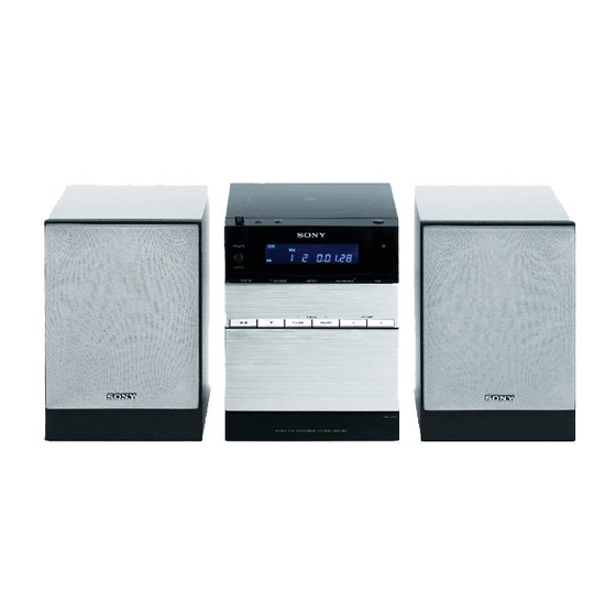
• CMT-DF1 is composed of following models.
As service manuals are issued for each component model,
please refer to them.
COMPONENT MODEL NAME
DVD Deck Receiver
Speaker System
SPECIFICATIONS
Power requirements
European and Russian models:
230 V AC, 50/60 Hz
Australian model:
230 – 240 V AC, 50/60 Hz
Korean model:
220 V AC, 60 Hz
Taiwan model:
120 V AC, 50/60 Hz
Other models:
120 V, 220 V, 230 – 240 V
AC, 50/60 Hz
Adjustable with voltage
selector
Power consumption:
30 watts
Dimensions (w/h/d) (excl. speakers):
Approx. 169 × 218 ×
201 mm
Mass (excl. speakers)
Approx. 2.6 kg
Supplied accessories:
Remote Commander (1)
R6 (size AA) batteries (2)
AM loop antenna (1)
FM lead antenna (1)
Video cord (1)
Design and specifications are subject to change
without notice.
Sony Corporation
9-887-490-03
Personal Audio Division
2007F05-1
Published by Sony Techno Create Corporation
© 2007.06
CMT-DF1
HCD-DF1
SS-CDF1
MICRO HI-FI COMPONENT SYSTEM
CMT-DF1
Australian Model
ACCESSORIES
Part No.
Description
1-480-286-11 COMMANDER, STANDARD (RM-SDF1)
1-751-619-13 CORD, CONNECTION (Video cord)
1-754-102-41 ANTENNA, LOOP (LW.MW) (AM loop antenna)
1-754-243-11 ANTENNA (FM lead antenna)
3-272-961-11 MANUAL, INSTRUCTION (ENGLISH)
3-272-961-21 MANUAL, INSTRUCTION (FRENCH, SPANISH) (AEP, E, SP)
3-272-961-31 MANUAL, INSTRUCTION (TRADITIONAL CHINESE)
3-272-961-51 MANUAL, INSTRUCTION (KOREAN) (KR)
3-272-961-61 MANUAL, INSTRUCTION (ARABIC) (E)
3-272-961-71 MANUAL, INSTRUCTION (GERMAN, DUTCH) (AEP)
3-272-961-81 MANUAL, INSTRUCTION (SWEDISH, POLISH) (AEP)
3-272-961-91 MANUAL, INSTRUCTION (RUSSIAN) (RU)
3-272-962-11 MANUAL, INSTRUCTION (ITALIAN) (AEP)
•
Abbreviation:
AUS : Australian model
HK : Hong Kong model
KR
: Korean model
RU
: Russian model
SP
: Singapore model
TW : Taiwan model
AEP Model
E Model
Remark
(AEP, RU, E, HK, SP, TW, AUS)
(HK, SP, TW)
Advertisement
Table of Contents

Related Manuals for Sony CMT-DF1


Summary of Contents for Sony CMT-DF1
- Page 1 CMT-DF1 SERVICE MANUAL AEP Model E Model Ver. 1.2 2007.06 Australian Model • CMT-DF1 is composed of following models. As service manuals are issued for each component model, please refer to them. COMPONENT MODEL NAME CMT-DF1 DVD Deck Receiver HCD-DF1...
- Page 2 CMT-DF1 REVISION HISTORY Clicking the version allows you to jump to the revised page. Also, clicking the version at the top of the revised page allows you to jump to the next revised page. Ver. Date Description of Revision 2006.11 2007.01...
- Page 3 SERVICE MANUAL AEP Model E Model Ver. 1.3 2007.10 Australian Model • HCD-DF1 is the amplifier, disc player, tape deck and tuner section in CMT-DF1. • This system incorporates Dolby Digital and DTS Digital Model Name Using Similar Mechanism Surround System.
-
Page 4: Table Of Contents
COMPONENTS IDENTIFIED BY MARK 0 OR DOTTED LINE WITH MARK 0 ON THE SCHEMATIC DIAGRAMS AND IN THE PARTS LIST ARE CRITICAL TO SAFE OPERATION. REPLACE THESE COMPONENTS WITH SONY PARTS WHOSE PART NUMBERS APPEAR AS SHOWN IN THIS MANUAL OR IN SUPPLEMENTS PUBLISHED BY SONY. -
Page 5: Servicing Notes
HCD-DF1 SECTION 1 SERVICING NOTES MODEL IDENTIFICATION NOTES ON HANDLING THE OPTICAL PICK-UP – Back Panel – BLOCK OR BASE UNIT The laser diode in the optical pick-up block may suffer electrostatic break-down because of the potential difference generated by the charged electrostatic load, etc. - Page 6 HCD-DF1 Playable discs Note on playback operations Discs that this system cannot of DVDs and VIDEO CDs play You can play back the following discs on this • CD-ROMs (except for extension “.MP3”, Some playback operations of DVDs and VIDEO system.
-
Page 7: General
HCD-DF1 SECTION 2 This section is extracted from instruction manual. GENERAL LOCATION OF CONTROLS Main unit ALPHABETICAL ORDER BUTTON DESCRIPTIONS A – O Disc operation buttons Z OPEN 8 Cassette compartment qg m/M (rewind/fast forward) qf Disc compartment 7 l/L (go back/forward) qf DISPLAY qs x (stop) wa Display window 6... -
Page 8: Disassembly
HCD-DF1 SECTION 3 DISASSEMBLY • This set can be disassembled in the order shown below. 3-1. DISASSEMBLY FLOW 3-2. PANEL LEFT, PANEL RIGHT (Page 6) 3-3. CABINET REAR BLOCK (Page 7) 3-4. CABINET FRONT BLOCK (Page 7) 3-6. MAIN BOARD 3-5. -
Page 9: Cabinet Rear Block
HCD-DF1 3-3. CABINET REAR BLOCK 6 connector (CN14) 5 connector (CON10: AEP, RU, E, HK, SP, TW and KR models, CON501: AUS model) 2 two screws (KTP2.6 × 6) 3 five screws (KTP2 3 × 8) 1 two screws (P2.6 × 8) 9 cabinet rear block 8 DVD/front cabinet block 7 connector... -
Page 10: Mech Deck (H-21), Deck Board
HCD-DF1 3-5. MECH DECK (H-21), DECK BOARD 6 DECK board 4 connector (CON101) 8 ground lead wire 5 three screws (BVTP2.6) 7 s crew 9 two screws (BVTP3 × 8) (BVTP3 × 8) 2 Cut the clamp. q; holder (PWB) 1 Remove the solder. -
Page 11: Op Assy (Khm-313Ahc)
HCD-DF1 3-7. OP ASSY (KHM-313AHC) qs flat type wire (24 core) (OP assy) 4 flat type wire (24 core) (DVD board) 1 connector qf OP assy (KHM-313AHC) qd two insulators qd two insulators qa connector q; plate DVD 3 sheet (DVD FFC) 8 four screws (P2 ×... -
Page 12: Test Mode
HCD-DF1 SECTION 4 SECTION 5 TEST MODE MECHANICAL ADJUSTMENTS INITIAL MODE SETTING PRECAUTION Procedure: 1. Clean the following parts with a denatured-alcohol-moistened 1. Press three buttons of [VOLUME +], [DISPLAY] and simultaneously. swab : 2. The system is initialized and turn the power on. record/playback head pinch roller (The function becomes tuner mode and the volume become... -
Page 13: Electrical Adjustment
HCD-DF1 SECTION 6 ELECTRICAL ADJUSTMENT 4. After the adjustments, apply suitable locking compound to DECK SECTION 0 dB=0.775 V the pats adjusted. 1. Demagnetize the record/playback head with a head Adjustment Location: Record/Playback/Erase Head demagnetizer. 2. Do not use a magnetized screwdriver for the adjustments. TEST TAPE Tape Signal... - Page 14 HCD-DF1 MEMO...
-
Page 15: Diagrams
HCD-DF1 SECTION 7 DIAGRAMS 7-1. BLOCK DIAGRAM – MAIN Section – FAN MOTOR INPUT SELECTOR, ELECTRICAL VOLUME IC102 (Page 14) POWER AMP IC101 DVD-L R-CH JA302 LINE AMP 13 TU-L LOUT 17 LIN O-LCH 10 IN1 OUT1 PHONES R-CH TA-L OPTICAL DIGITAL OUT MUTING... -
Page 16: Block Diagram - Panel/Power Supply Section
HCD-DF1 7-2. BLOCK DIAGRAM – PANEL/POWER SUPPLY Section – LIQUID CRYSTAL DISPLAY DRIVER SYSTEM CONTROLLER U1 (2/2) FAN MOTOR SD_DATA BU9728_DATA DRIVE SEG1 – QT2, QT4 BU9728_CLK SEG30 LCD1 BU9728_CE FAN MOTOR (FAN) LIQUID C/D_STB BU9728_C/D_STB CRYSTAL OPTION_IN (Page 13) DISPLAY COM1 –... - Page 17 HCD-DF1 • Note for Printed Wiring Boards and Schematic Diagrams • Circuit Boards Location Note on Printed Wiring Board: Note on Schematic Diagram: • X : parts extracted from the component side. • All capacitors are in µF unless otherwise noted. (p: pF) •...
-
Page 18: Printed Wiring Board - Deck Board
HCD-DF1 • See page 15 for Circuit Boards Location. 7-3. PRINTED WIRING BOARD – DECK Board – : Uses unleaded solder. • Semiconductor Location Ref. No. Location DECK BOARD (REC/PB) R194 C188 C190 R180 C178 R195 R196 R183 R174 C172 C198 C184 C203... -
Page 19: Schematic Diagram - Deck Board
HCD-DF1 • See page 28 for IC Block Diagrams. 7-4. SCHEMATIC DIAGRAM – DECK Board – C234 0.022 R166 C235 330p C237 100p C233 R167 R169 0.01 5.6k 2SC3052 C191 C189 T101 C232 R168 0.0033 390p 470p BIAS OSC R181 L101 Q25,27 SW5(2/9) -
Page 20: Printed Wiring Board - Microphone Board
HCD-DF1 7-5. PRINTED WIRING BOARD – MICROPHONE Board – 7-6. SCHEMATIC DIAGRAM – MICROPHONE Board – • See page 15 for Circuit Boards Location. : Uses unleaded solder. JA302 JA303 PHONES MICROPHONE BOARD CE301 R302 CE301 CE304 R308 2.2k R308 CE302 C310 R315... -
Page 21: Printed Wiring Board - Main Board
HCD-DF1 • See page 15 for Circuit Boards Location. 7-7. PRINTED WIRING BOARD – MAIN Board – : Uses unleaded solder. • Semiconductor (Page 18) Location COMPONENT VIDEO OUT MICROPHONE S VIDEO OUT BOARD Ref. No. Location (FAN) VIDEO OUT SPEAKER DIGITAL OUT DVD BOARD... -
Page 22: Schematic Diagram - Main Board (1/4)
HCD-DF1 • See page 28 for IC Block Diagrams. 7-8. SCHEMATIC DIAGRAM – MAIN Board (1/4) – (1/4) MOTO+ MOTO-SW TAPE MECHA INPUT SELECTOR,ELECTRICAL VOLUME DECK BLOCK MOTO-SW IC102 (2/2) PT2314 0.022 10 50V CON9 CON1 RLS4148 CON15 VCC CONT 0.027 MUTE TREB-L... -
Page 23: Schematic Diagram - Main Board (2/4)
HCD-DF1 • See page 28 for IC Block Diagrams. 7-9. SCHEMATIC DIAGRAM – MAIN Board (2/4) – (2/4) R103 2.2k C120 (AEP,RU,KR) POWER AMP CON2 2SC5938 STADBY PH-R 0.47 1000 STANDBY SWITCH SP-R R106 OUT1 (Page 20) IC101 SP-L 220p LA4600 2.2k 0.01... -
Page 24: Schematic Diagram - Main Board (3/4)
HCD-DF1 • See page 28 for Waveforms. • See page 28 for IC Block Diagrams. 7-10. SCHEMATIC DIAGRAM – MAIN Board (3/4) – (3/4) CON6 CON5 VIDEO QT2,QT4 GND(AV_GND) FAN MOTOR DRIVE (FAN) RT12 GND(AV_GND) ISA1235 YUV_V BOARD YUV_Y RT10 4.7K (3/4) YUV_U... -
Page 25: Schematic Diagram - Main Board (4/4)
HCD-DF1 • See page 28 for Waveforms. • See page 28 for IC Block Diagrams. • See page 30 for IC Pin Function Description. 7-11. SCHEMATIC DIAGRAM – MAIN Board (4/4) – (4/4) CON23 CON13 CON17 2SC3052 INVERTER C105 SYSTEM CONTROLLER RLS4148 3P70F4XZZ-S094 CON09... -
Page 26: Printed Wiring Board - Panel Board
HCD-DF1 • See page 15 for Circuit Boards Location. 7-12. PRINTED WIRING BOARD – PANEL Board – : Uses unleaded solder. J210 R262 R263 R265 R266 R264 C216 KEY1 – KEY11 R261 C217 PANEL BOARD MAIN BOARD (Page 19) CON12 J209 (LCD BACK LIGHT) CON11... -
Page 27: Schematic Diagram - Panel Board
HCD-DF1 • See page 28 for Waveforms. • See page 28 for IC Block Diagrams. 7-13. SCHEMATIC DIAGRAM – PANEL Board – LCD1 LIQUID CRYSTAL DISPLAY REMOTE CONTROL RECEIVER RPM7240-H9 C223 C212 R240 R239 0.01 CON11 VCC_3.3V REMOTE C/D_STB BU9728_DATA BU9728_CE BU9728_CLK (Page 23) -
Page 28: Printed Wiring Boards - Power Supply Section
HCD-DF1 • See page 15 for Circuit Boards Location. 7-14. PRINTED WIRING BOARDS – POWER SUPPLY Section – : Uses unleaded solder. (AUS) (AC IN) POWER BOARD AEP, RU, E, HK, SP, TW, KR AEP, RU, E, HK, SP, TW, KR (AUS) (TW) (E, HK, SP) -
Page 29: Schematic Diagram - Power Supply Section
HCD-DF1 7-15. SCHEMATIC DIAGRAM – POWER SUPPLY Section – (AUS) CON501 T2AL 250V POWER TRANSFORMER CN14 T0.63AL (AEP,RU,AUS) 250V J504 T2AL 250V (AEP,RU,E,HK,SP,TW,KR) (AC IN) (KR) J503 J506 (AUS) (Page 21) J505 J507 (TW) J502 J501 (AEP,RU,E,HK,KR,AUS) (E,HK,SP) CON10 VOLTAGE SELECTOR 120V 220V... - Page 30 HCD-DF1 • Waveforms IC102 PT2314 – MAIN Board – – PANEL Board – U3 3 (SW) (DVD play mode) IC2 2 (OSC2) 14 13 11 10 9 8 TREBLE 4.3 Vp-p 15.6 Vp-p 2.5 µ s 25.6 µ s VOLUME & SERIAL BUS 5 V/DIV, 1 µ...
- Page 31 HCD-DF1 U3 MP1580HS-LF-Z BS 1 CURRENT IN 2 Σ SENSE SYNC OSCILLATOR AMPLIFIER 40/380kHz INTERNAL REGULATORS SHUTDOWN COMPARATOR FREQUENCY FOLDBACK CURRENT COMPARATOR COMPARATOR SW 3 LOCKOUT COMPARATOR GND 4 COMP ERROR AMPLIFIER – PANEL Board – IC2 BU9728AKV-E2 48 – 37 OSC1 TIMING COMMON...
- Page 32 HCD-DF1 • IC Pin Function Description MAIN BOARD U1 3P70F4XZZ-S094 (SYSTEM CONTROLLER) Pin No. Pin Name Description Ground terminal XOUT System clock output terminal (4.19 MHz) System clock input terminal (4.19 MHz) TEST Test signal input terminal Not used REMOTE SIRCS signal input from the remote control receiver DVD_STB Strobe signal input from the DVD block...
-
Page 33: Exploded Views
HCD-DF1 SECTION 8 EXPLODED VIEWS NOTE: • -XX and -X mean standardized parts, so they • Items marked “*” are not stocked since they KR : Korean model are seldom required for routine service. Some RU : Russian model may have some difference from the original one. -
Page 34: Panel Board Section
HCD-DF1 Ver. 1.3 8-2. PANEL BOARD SECTION not supplied (POWER not supplied SWITCH board) CON11 not supplied not supplied (MICROPHONE board) not supplied PANEL board TAPE deck section Ref. No. Part No. Description Remark Ref. No. Part No. Description Remark 3-196-216-01 PLATE (OPERATION AL) A-1283-893-A PANEL BOARD, COMPLETE 3-273-018-01 SHEET (OPERATION AL) -
Page 35: Tape Deck Section
HCD-DF1 8-3. TAPE DECK SECTION not supplied not supplied (DECK board) not supplied not supplied supplied supplied Ref. No. Part No. Description Remark Ref. No. Part No. Description Remark 3-196-184-01 COVER CASSETTE 2-670-389-01 BELT (1) 3-215-196-01 SPRING (CASSETTE) 3-214-987-01 SHEET (AZIMUTH) 3-196-218-01 SPRING (PLATE CASSETTE) 3-196-215-01 PLATE (CASSETTE AL) 3-196-191-01 PLATE (CASSETTE BUTTON) -
Page 36: Dvd Section
HCD-DF1 Ver. 1.3 8-4. DVD SECTION not supplied S101 not supplied not supplied not supplied not supplied not supplied (MAIN board) not supplied Ref. No. Part No. Description Remark Ref. No. Part No. Description Remark 3-087-053-01 SCREW +BVTP 2.6 (3CR) 1-693-734-11 TUNER (FM/AM) (E, HK, SP, TW, AUS) 1-693-735-11 TUNER (FM/AM) (AEP, RU, KR) 0 165... -
Page 37: Cabinet Rear Section
HCD-DF1 8-5. CABINET REAR SECTION not supplied not supplied (POWER board) not supplied not supplied not supplied not supplied Ref. No. Part No. Description Remark Ref. No. Part No. Description Remark 1-500-868-11 CORE, FERRITE 4-237-065-01 CLAMP (L35) 3-918-696-11 SCREW (M3X6 LOCK ACE) 3-701-748-00 CLAMP 0 F1 3-564-708-01 SCREW (+P 2X18) (TYPE 2) -
Page 38: Electrical Parts List
HCD-DF1 SECTION 9 DECK ELECTRICAL PARTS LIST NOTE: • Due to standardization, replacements in the • RESISTORS : Singapore model parts list may be different from the parts All resistors are in ohms. : Taiwan model specified in the diagrams or the components METAL: Metal-film resistor. - Page 39 HCD-DF1 Ver. 1.3 DECK MAIN Ref. No. Part No. Description Remark Ref. No. Part No. Description Remark R179 1-216-841-11 METAL CHIP 1/10W 1-126-935-11 ELECT 470uF R180 1-216-841-11 METAL CHIP 1/10W 1-126-934-11 ELECT 220uF R181 1-216-832-11 METAL CHIP 8.2K 1/10W 1-126-935-11 ELECT 470uF R182 1-216-832-11 METAL CHIP...
- Page 40 HCD-DF1 MAIN Ref. No. Part No. Description Remark Ref. No. Part No. Description Remark 1-164-227-11 CERAMIC CHIP 0.022uF C135 1-162-965-11 CERAMIC CHIP 0.0015uF 10% 1-164-227-11 CERAMIC CHIP 0.022uF 1-126-933-11 ELECT 100uF C136 1-162-965-11 CERAMIC CHIP 0.0015uF 10% C137 1-131-664-91 CERAMIC CHIP 0.15uF 1-126-947-11 ELECT 47uF...
- Page 41 HCD-DF1 MAIN Ref. No. Part No. Description Remark Ref. No. Part No. Description Remark IC102 6-702-842-01 IC PT2314 1-216-809-11 METAL CHIP 1/10W 1-216-853-11 METAL CHIP 470K 1/10W < JACK/TERMINAL/IC > 1-216-829-11 METAL CHIP 4.7K 1/10W JAC1 1-774-227-11 JACK, PIN 1P (VIDEO OUT) 1-216-829-11 METAL CHIP 4.7K 1/10W...
- Page 42 HCD-DF1 MAIN MICROPHONE Ref. No. Part No. Description Remark Ref. No. Part No. Description Remark 1-216-829-11 METAL CHIP 4.7K 1/10W 1-216-864-11 SHORT CHIP 1-216-829-11 METAL CHIP 4.7K 1/10W 1-216-864-11 SHORT CHIP 1-216-849-11 METAL CHIP 220K 1/10W 1-216-849-11 METAL CHIP 220K 1/10W 1-216-864-11 SHORT CHIP 1-216-833-11 METAL CHIP...
- Page 43 HCD-DF1 MICROPHONE PANEL POWER Ref. No. Part No. Description Remark Ref. No. Part No. Description Remark < JACK > < RESISTOR> JA302 1-815-629-11 JACK (PHONES) J207 1-249-409-11 CARBON 1/4W JA303 1-815-629-11 JACK (MIC) < SWITCH > < TRANSISTOR > KEY1 1-762-875-21 SWITCH, KEYBOARD (x) Q301 8-729-120-28 TRANSISTOR...
- Page 44 HCD-DF1 Ver. 1.3 POWER POWER SWITCH Ref. No. Part No. Description Remark Ref. No. Part No. Description Remark < FUSE > 0 F1 1-532-500-33 FUSE (T0.63AL/250V) 0 F2 1-532-388-33 FUSE (T2AL/250V) 0 F3 1-532-388-33 FUSE (T2AL/250V) < FUSE HOLDER > 1-533-217-41 HOLDER, FUSE 1-533-217-41 HOLDER, FUSE 1-533-217-41 HOLDER, FUSE...
- Page 45 HCD-DF1 MEMO...
- Page 46 HCD-DF1 REVISION HISTORY Clicking the version allows you to jump to the revised page. Also, clicking the version at the top of the revised page allows you to jump to the next revised page. Ver. Date Description of Revision 2006.11 2007.01 Addition of AEP and Russian models 2007.06...
- Page 47 SS-CDF1 SERVICE MANUAL AEP Model E Model Ver. 1.2 2007.06 Australian Model • SS-CDF1 is the speaker system in CMT-DF1. SPECIFICATIONS PARTS LIST Speaker system Full range, bass-reflex Part No. Description Remark type, magnetically A-1283-796-A OVERALL ASSY shielded type Speaker units...
- Page 48 SS-CDF1 REVISION HISTORY Clicking the version allows you to jump to the revised page. Also, clicking the version at the top of the revised page allows you to jump to the next revised page. Ver. Date Description of Revision 2006.11 2007.01 Addition of AEP and Russian models 2007.06...
Need help?
Do you have a question about the CMT-DF1 and is the answer not in the manual?
Questions and answers