
Related Manuals for JYTEK PCIe-67432

Summary of Contents for JYTEK PCIe-67432
- Page 1 PCIe-67432 32CH Isolated DI/32CH Isolated DO PCIe Card Manual Rev.: 1.00 Revision Date: Mar. 2, 2020 Advance Technologies; Automate the World.
- Page 3 Restriction of Hazardous Substances (RoHS) directive and Waste Electri- cal and Electronic Equipment (WEEE) directive. Environmental protec- tion is a top priority for JYTEK. We have enforced measures to ensure that our products, manufacturing processes, components, and raw materials have as little impact on the environment as possible. When...
- Page 4 Conventions Take note of the following conventions used throughout this manual to make sure that users perform certain tasks and instructions properly. Additional information, aids, and tips that help users perform tasks. NOTE: NOTE: Information to prevent minor physical injury, component damage, data loss, and/or program corruption when trying to complete a task.
-
Page 5: Table Of Contents
Table of Contents Preface ..................iii Table of Contents................v List of Figures ................vii List of Tables .................. ix 1 Introduction................1 Features ..................1 Applications ................... 1 Specifications ................. 1 Software Support................3 PCIS-DASK .................3 PCB Layout ..................3 Connectors.................. - Page 6 Initial ..................13 Digital Input Relative Functions ..........14 Digital Output Relative Functions .......... 15 Interrupt Source Control ............15 Get Interrupt Status ............... 16 Interrupt Enable ..............17 Interrupt Disable ..............17 Important Safety Instructions ............19 Getting Service ................21 Table of Contents...
-
Page 7: List Of Figures
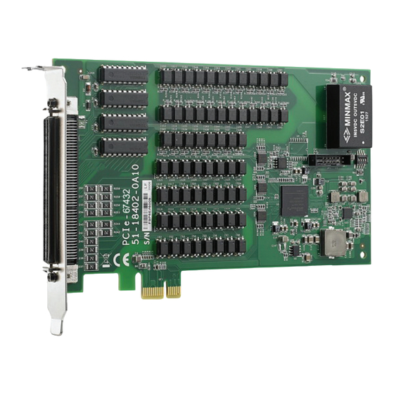
List of Figures Figure 1-1: PCIe-67432 Board Layout............3 Figure 1-2: PCIe-67432 CN1 Connector............4 Figure 1-3: Isolated Input Connection............7 Figure 1-4: Common Ground Connection ...........8 List of Figures... - Page 8 This page intentionally left blank. viii List of Figures...
-
Page 9: List Of Tables
List of Tables Table 1-1: PCIe-67432 CN1 Pin Assignment..........6 Table 3-1: I/O Register Map ..............11 Table 3-2: IDI_N: Isolated Digital Input CH N ...........11 Table 3-3: IDI_N: Isolated Digital Input CH N ...........12 List of Tables... - Page 10 This page intentionally left blank. List of Tables...
-
Page 11: Introduction
Introduction JYTEK'S PCIe-67432 for PCIe bus provides 32CH isolated DI and 32CH iso- lated DO and robust 2,500V isolation protection, suitable for most industrial applications. All digital input channels are identical non-polar and opto-isolated. All channels are isolated and suitable for collecting digital inputs in noisy environments. - Page 12 1.3.1 Digital Input Input Channels Photocoupler HCPL-814 10 mA rated Input current 20 mA max. for isolated input Up to 24V DC or 24V AC Input voltage Logic Low: 0 to 1.5V Logic High 5 to 24V Input impedance 2.4kΩ @ 0.5W Interrupt Sources Digital input channels 0 and channel 1 Isolated voltage...
-
Page 13: Software Support
In addition to programming libraries such as DLLs for most Windows-based systems, JYTEK also provides drivers for other application environments. Be sure to install the driver & utility before using the PCIe-67432. PCIS-DASK PCIS-DASK consists of advanced 32/64-bit kernel drivers and SDK for... -
Page 14: Connectors
Connectors The PCIe-67432 is equipped with a 100-pin SCSI connector (CN1). Figure 1-2: PCIe-67432 CN1 Connector IDI_0 IDI_8 IDI_1 IDI_9 IDI_2 IDI_10 IDI_3 IDI_11 Introduction... - Page 15 IDI_4 IDI_12 IDI_5 IDI_13 IDI_6 IDI_14 IDI_7 IDI_15 COM1 COM2 COM1 COM2 COM1 COM2 COM1 COM2 IDI_16 IDI_24 IDI_17 IDI_25 IDI_18 IDI_26 IDI_19 IDI_27 IDI_20 IDI_28 IDI_21 IDI_29 IDI_22 IDI_30 IDI_23 IDI_31 COM3 COM4 COM3 COM4 COM3 COM4 COM3 COM4 IDO_0 IDO_8 IDO_1...
-
Page 16: Di/O Channels
Isolated digital input has an open collector transistor structure with voltage range 0V to 24V and input resistance of 2.4kΩ. Connection between external signals and the PCIe-67432 is as shown in Fig A01. Since input common junction can be common ground in the environ- ment, digital input can be either a current source or a current sink. -
Page 17: Isolated Digital Output Channels
Isolated Input 2.4k Signal (source) Current Dir. COM m (GND) Isolated Input 2.4k Signal (sink) Current Dir. COM m (+VDD) Figure 1-3: Isolated Input Connection Isolated Digital Output Channels Common ground connection of the isolated digital output is as shown. When isolated digital output is ON, sink current is through transistors, and when OFF, none is. -
Page 18: Figure 1-4: Common Ground Connection
DC-DC Converter Load 5 to 35V IGND Figure 1-4: Common Ground Connection Introduction... -
Page 19: Getting Started
Retain the shipping carton and packing materials for inspection. Obtain authorization from your dealer before returning any product to JYTEK. Ensure that the following items are included in the package. PCIe-67432 high-speed DI/O card ... - Page 20 Configuration All PCI/PCIE Express cards on your system are configured individually. Because configuration is controlled by the system and the software, no jumper setting is required for base address, DMA, and interrupt IRQ. Configuration is subject to change with every boot of the system as new ®...
-
Page 21: Register Format
PCIe interface. I/O Address Map As PCIe-67432 registers are 32 bits long, they are accessible via 32-bit I/ O instruction. The register address map, including descriptions and off- set addresses relative to the base address, is as follows. -
Page 22: Digital Output Register
Digital Output Register Each bit of based address corresponds to a signal on one of the 32 digi- tal output channels. Address: BASE + 0 to BASE + 3 for 67432 Attribute: Write Only Data format: 7432 Base + 0 IDO_7 IDO_6 IDO_5... -
Page 23: Appendixa C/C++ Dos Function Library
Digital Output Relative Functions Interrupt Source Control Get Interrupt Status Interrupt Enable Interrupt Disable Initial Initializes all installed PCIe-67432 cards. Plug and play capability allows IRQ and I/O address to be assigned by the system BIOS directly. C/C++ DOS Function Library... -
Page 24: Digital Input Relative Functions
Visual Basic (Windows) W_7432_Initial (existCards As Integer, info As PCI_INFO) As Integer Argument existCards: The number of installed PCIe-67432 cards. Pciinfo: Records PCIe bus plug and play initialization information as set by p&p BIOS. PCIe_INFO structure is defined in ACL_PCI.H, with base I/O address and interrupt channel number are stored in pciinfo for reference. -
Page 25: Digital Output Relative Functions
Return Code ERR_NoError ERR_BoardNoInit Digital Output Relative Functions Write data to the digital output ports (to write 32-bit data, call function _7432_DO). Syntax C/C++ (DOS) U16 _7432_DO (U16 cardNo, U32 do_data) C/C++ (Windows) U16 W_7432_DO (U16 cardNo, U32 do_data) Visual Basic (Windows) W_7432_DO (ByVal cardNo As Integer, ByVal do_data As Long) As Integer Argument cardNo: Card number of selected board... -
Page 26: Get Interrupt Status
C/C++ (Windows) void W_7432_Set_INT_Control (U16 cardNo, U16 int1Flag, U16 int2Flag) Visual Basic (Windows) W_7432_Set_INT_Control (ByVal cardNo As Integer, ByVal int1Flag As Integer, ByVal int2Flag As Integer) Argument cardNo: Card number of selected board int1Flag: INT1 setting; 0: disable, 1: enable int2Flag: INT2 setting;... -
Page 27: Interrupt Enable
Return Code ERR_NoError ERR_BoardNoInit Interrupt Enable Activates the interrupt controller. After calling, software signals every interrupt request signal generated. Refer to sample pro- gram 7432int.c. Syntax C/C++ (Windows) U16 W_7432_INT_Enable (U16 cardNo, HANDLE *hEvent) Visual Basic (Windows) W_7432_INT_Enable (ByVal cardNo As Integer, hEvent As Long) As Integer Argument cardNo: Card number of selected board... - Page 28 Return Code ERR_NoError ERR_BoardNoInit C/C++ DOS Function Library...
-
Page 29: Important Safety Instructions
Important Safety Instructions For user safety, please read and follow all instructions, WARNINGS, CAUTIONS, and NOTES marked in this manual and on the associated equipment before handling/operating the equipment. Read these safety instructions carefully. Keep this user’s manual for future reference. ... - Page 30 Never attempt to fix the equipment. Equipment should only be serviced by qualified personnel. A Lithium-type battery may be provided for uninterrupted, backup or emergency power. Risk of explosion if battery is replaced with one of an incorrect type. Dispose of used batteries appropriately.
-
Page 31: Getting Service
Getting Service Address: (201203) 300 Fang Chun Rd., Zhangjiang Hi-Tech Park Pudong New Area, Shanghai, 201203 China Tel: +86-21-5 Fax: Email: Getting Service... - Page 32 Getting Service...
Need help?
Do you have a question about the PCIe-67432 and is the answer not in the manual?
Questions and answers