Table of Contents
Advertisement
Quick Links
Abrasive Blasters 1.5 - 20 c.f. (MV3)
OPERATION AND MAINTENANCE MANUAL
June 2021
SAVE THIS MANUAL AND MAKE AVAILABLE
TO ALL USERS OF THIS EQUIPMENT!
Manual Part Number 7200-200MV
(Scan QR tag below for downloading from SchmidtAbrasiveBlasting.com)
XX
Copyright © 2021 A
IOM Manufacturing, Inc.
11927 S. Highway 6, Fresno, Texas 77545
800.231.2085 * 281.431.0581 * fax 281.431.1717
Visit us at www.SchmidtAbrasiveBlasting.com
Website
Manual
Advertisement
Table of Contents

Subscribe to Our Youtube Channel
Related Manuals for Schmidt MV3


Summary of Contents for Schmidt MV3
- Page 1 Abrasive Blasters 1.5 - 20 c.f. (MV3) OPERATION AND MAINTENANCE MANUAL June 2021 SAVE THIS MANUAL AND MAKE AVAILABLE TO ALL USERS OF THIS EQUIPMENT! Manual Part Number 7200-200MV (Scan QR tag below for downloading from SchmidtAbrasiveBlasting.com) Copyright © 2021 A IOM Manufacturing, Inc.
- Page 2 8. Do Not modify or alter any abrasive blaster, blast equipment or controls thereof without written consent from Axxiom Manufacturing, Inc. 9. Do Not use bleeder type deadman valves on any Schmidt® abrasive blaster. The use of A-BEC, Clemco or a similar bleeder type deadman valve can cause unintentional start-up without warning, which can result in serious personal injury.
- Page 3 Instructions for use of manual sections This manual contains information needed to operate and maintain your abrasive blaster. Read this entire operations and maintenance manual before using your abrasive blaster. Pay close attention to the Rules for Safer Operation (Section 1.0), and the Dangers, Warnings, and Cautions identified. The purpose of safety symbols and explanations are to alert you of the possible hazards and explain how to avoid them.
-
Page 4: Warning Decal Identification And Location
Figure 0.1(a) and 0.1(b) for images of the warning decals. Refer to Figure 0.2(a) and 0.2(b) for the locations of these warning decals on the abrasive blaster. Qty. Part no. Description Hazard 7031-001 Medium “Schmidt” Not Applicable 7031-002 Small “Schmidt” Airborne particles and loud noise from blast “Warning” nozzle and blowdown can cause injury and... - Page 5 5) 7031-077 6) 7031-082 7) 7034-001 (welded) 7) 7031-084 (decal) (Units manufactured after July 2017) Figure 0.1(b) – Warning decal summary (continued) Copyright © 2021 Axxiom Manufacturing, Inc.
- Page 6 Figure 0.2(a) – Warning decal placement (1.5 cu. ft.) Figure 0.2(b) – Warning decal placement (3.5 - 20 cu. ft.) Copyright © 2021 Axxiom Manufacturing, Inc.
-
Page 7: Table Of Contents
Warning Decal Identification and Location Rules for Safer Operation Specifications and General Information Installation Requirements and Personal Protective Equipment Abrasive Blast System General Operation MV3 Blast System General Operation Pre-operation Procedures Operating Instructions Maintenance and Inspection Instructions Drawings and Parts Lists 10.0... -
Page 8: Rules For Safer Operation
Do Not operate this equipment in a manner other than its intended application (see Section 4.0). Do Not operate this equipment or any other Schmidt® equipment without following the Rules for Safer Operation and all the operating procedures and instructions. Learn the applications and limitations as well as the specific potential hazards related to this machine. - Page 9 1.5. PROTECT YOUR EYES. Do Not operate this equipment without wearing OSHA approved safety glasses. Observe all applicable local, state, and federal safety regulations. See Section 3.10 and OSHA 29 CFR 1910.133. When filling the blast vessel and during the blast operation, abrasive can be blown in the face and eyes of operators.
- Page 10 1.8. PROTECT YOUR HEARING. Do Not operate this equipment without wearing OSHA approved hearing protection. Observe all applicable local, state and federal safety regulations. See Section 3.10 and refer to OSHA 29 CFR 1926.101 and 1910.95. Loud noise is produced by the blast nozzle and the blowdown operation of this equipment. All operators and personnel in the vicinity must wear OSHA approved hearing protection during the operation of this equipment.
- Page 11 1.17. AVOID DANGEROUS ENVIRONMENTS. Do Not operate this equipment in elevated areas without using fall protection equipment. Certain applications of this equipment may require the use of scaffolding. Use of scaffolding creates hazardous situations such as tripping and fall hazards which can result in serious injury or death to operating personnel.
- Page 12 1.25. NEVER OPERATE BEYOND ALLOWABLE TEMPERATURE RANGE. Do Not operate this equipment above the maximum allowable temperature at the allowable pressure or below the minimum design metal temperature (MDMT) shown on the pressure vessel nameplate. The characteristics of the pressure vessel metal are weakened when the temperature is outside the operating range.
- Page 13 Reference OSHA 29 CFR 1910.244(b). 1.36. NEVER USE BLEEDER TYPE DEADMAN VALVES. Do Not use bleeder type deadman valves on any Schmidt® abrasive blaster. The use of A-BEC, Clemco, or a similar bleeder type deadman valve can, without warning, cause unintentional start-up which can result in serious personal injury.
- Page 14 1.40. ALWAYS USE CORRECT PRESSURE RATED ACCESSORIES. Do Not use air reservoirs or moisture separator tanks that are not rated for use in compressed air applications. Air reservoirs and moisture separator tanks larger than 6 inches inside diameter must have an ASME code stamp. An air reservoir or moisture separator tank is a Pressurized Vessel.
-
Page 15: Specifications And General Information
See the lifting diagrams shown in Section 2.6. 2.1.5. For further information on options and accessories available for Schmidt® abrasive blasters visit the Axxiom website or contact us: Axxiom Manufacturing, Inc. - Page 16 Vessel Information 2.4.1. All pressure vessels used in Schmidt® Abrasive Blasters are manufactured in strict accordance with the provisions of the ASME Code Section VIII, Div. 1. 2.4.2. To maintain the high level of quality and quality control used in the manufacture of this vessel, it is required that all welded repairs to this vessel be performed by a reputable shop holding a National Board “R”...
- Page 17 *All weights are approximate and include piping. Figure 2.6(b) – Abrasive Blaster Dimensional Data Copyright © 2021 Axxiom Manufacturing, Inc.
- Page 18 Abrasive Blaster Strapping / Packing Detail Copyright © 2021 Axxiom Manufacturing, Inc.
-
Page 19: Installation Requirements And Personal Protective Equipment
(depressurization). See Section 5.5 for system depressurization. A longer exhaust hose assembly can be installed on MV3 Blast Systems to direct the exhaust air into the blast room. Note: A longer blowdown exhaust hose can lengthen the blowdown time and creates the possibility of blockage. - Page 20 Blast System Air Supply Line The air supply hose and fittings must be rated at a minimum of 150 psi operating pressure. The air supply hose from the air compressor to the blast unit should be at least the same diameter as the air inlet piping (see Section 9.0).
- Page 21 (i.e. coalescing moisture separator, air-cooled aftercooler or deliquescent dryer). Contact a local authorized Schmidt® distributor or Axxiom Manufacturing, Inc. to locate one near you.
- Page 22 Use these sources to obtain information regarding all aspects of surface preparation and abrasive selection guidelines. Schmidt® abrasive blasters are designed for high production open abrasive blasting with a wide range of abrasives. It is the responsibility of the employer and operators to select the proper abrasive.
- Page 23 3.10 Personal Protective Equipment (PPE) Abrasive blasting has many hazards that may cause injuries to operators. To minimize risk of injury to operators, each must be supplied with, and required to use Personal Protective Equipment. The Occupational Health and Safety Administration (OSHA) requires the employer to assess the workplace to determine what PPE is necessary and supplied to each operator (Reference 29 CFR 1910 Subpart I).
- Page 24 3.11 Pressure Relief Valve Installation Do Not operate this equipment without a pressure relief device installed to protect the blaster pressure vessel from over-pressurization. The ASME Code requires that all vessels be operated with pressure relief devices in place. If the compressed air system does not provide for the installation of a pressure relief valve one can be installed on the pressure vessel piping.
- Page 25 3.12 INSTALLATION CHECKLIST (Photocopy this page to use as a worksheet) □ Deadman/Twinline (or cords): confirm delivery with the abrasive blaster. □ Blast accessories: confirm receipt as purchased with the blaster. □ Inspect blaster: check for possible damage during shipment. See Section 8.0 for inspection instructions.
-
Page 26: Abrasive Blast System General Operation
Since moisture creates problems in the blast operation, it is common for the compressed air to be fed through a moisture removal device, such as a Schmidt AirPrep System. The air pressure in the abrasive blast vessel is equal to the air pressure in the blast hose where it connects at the metering valve. -
Page 27: Mv3 Blast System General Operation
Abrasive will flow through the MV3 Valve (#14) and fall into the blast air stream. The abrasive flow can be increased or decreased by turning the knob on top of the MV3 Valve (#14). Because of the length of the blast hose, it will take a few seconds to see changes in abrasive flow. - Page 28 When the inlet ball valve is opened, air will flow through the moisture separator (#7) and into the ComboValve® (#4). In a properly operating MV3 Valve / ComboValve system the blast vessel does not pressurize when the inlet ball valve is opened.
- Page 29 MV3 Valve (#14) orifice. Whenever trash (paint chips, cigarette butts, etc.) blocks the MV3 Valve orifice the procedure is to fully open the MV3 Valve by backing out the knob, then press down the deadman lever (#12) to begin blasting. While blasting, have an assistant close the choke valve completely for about one second.
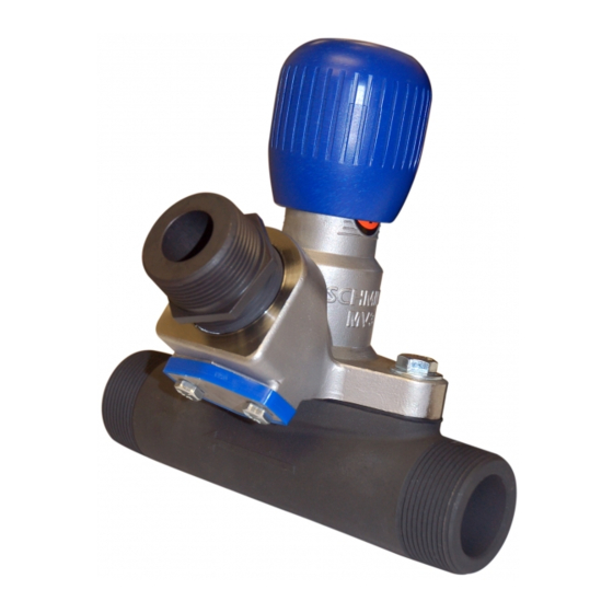
- Page 30 The MV3 Valve (#14) is used to control (meter) abrasive flow by use of an adjustable orifice. The size of this orifice is controlled by turning the knob at the top of the MV3 Valve. Turning the knob clockwise reduces the orifice size which decreases abrasive flow. Turning the knob counterclockwise increases the orifice size which will increase the abrasive flow to the blast nozzle (#11).
- Page 31 Figure 5.4 – MV3 Valve Electric Deadman Blast Control System MV3 Valve Abrasive Blaster with Electric Control System Figure 5.5 shows a MV3 Valve abrasive blaster with the electric deadman system. The popup valve, MV3 Valve, and ComboValve operate the same as a blaster with a pneumatic blast control system.
- Page 32 5.10 Blast Hose The blast air and abrasive mixture flows from the MV3 Valve (#14) to the blast nozzle (#11) through the blast hose assembly (#10). The typical length of the blast hose is 50ft; however, blast hose extensions can be added to increase length. For higher efficiency keep the blast hose as short as possible.
- Page 33 5.13 Union End Ball Valve (optional) The union ball valve is used to block the abrasive flow to the MV3 Valve. This allows the user to remove the MV3 Valve from the blast vessel without emptying the abrasive. Turn the union ball valve handle to the horizontal position to block abrasive flow.
- Page 34 The standard blowdown hose must be shortened to 14-1/2” to accommodate the VBS II System. Note: The VBS is standard on MV3 / ComboValve package blasters manufactured after June 2011 (except for 1.5cf). Conversion kits are available for field addition of the VBS II System.
- Page 35 5.17 Options and Accessories There are many options, accessories, and field conversion kits available to upgrade Schmidt® abrasive blasters. Options include the new Universal Load Skid, abrasive screen, lid or the new hinged lid, abrasive spider, angle flange, door interlock, air pressure regulator, blast hour meter, “Short Stop”...
- Page 36 THIS PAGE IS INTENTIONALLY BLANK Copyright © 2021 Axxiom Manufacturing, Inc.
-
Page 37: Pre-Operation Procedures
Pre-operation Procedures Failure to follow the procedures below could result in serious injury or death. In addition to these procedures completely read and understand all sections of this Abrasive Blaster Operation and Maintenance Manual. The Abrasive Blaster is a pressurized vessel. Propelled objects will cause serious injury or death. Depressurize vessel before performing any maintenance. - Page 38 6.1.6. Verify that all required personal protective equipment is available for each operator and in good operating condition (safety glasses, safety shoes, ear plugs, gloves, airline filter, respirator, & carbon monoxide monitor). Critical: Adhere to all local, state, and federal regulations including, but not limited to, OSHA (Occupational Health and Safety Administration).
- Page 39 Abrasive Blaster Depressurizing Procedure A MV3 Valve blaster is a depressurized system; meaning that the blaster will depressurize when the deadman (#12) is released. 6.2.1. Release the deadman (#12) to deactivate the ComboValve® (#4) and depressurize the abrasive blaster. The blast operation will stop.
- Page 40 6.3.13. Periodically check for leaks. *Note: Contact Axxiom Manufacturing or an Authorized Schmidt distributor and request information on the new SureFit™ Handway Gasket (patent pending) that eliminates the difficulty of aligning the gasket. Scan the QR Tag on the left to view a short video.
- Page 41 Figure 6.3 (a) – Handway Assembly Figure 6.3 (b) – Handway Components 6” x 8” Handway Dimensions Component Weld Ring 6-5/8” 8-1/2” Handway Cover 7-5/8” 9-3/4” Handway Gasket 7-3/4” 9-3/4” SureFit™ Gasket 8-1/16” 10-5/16” Handway Crab 2-3/8” 8-3/4” Square Head Bolt 3/4”-10 UNC 4-1/2”...
-
Page 42: Operating Instructions
7.1.4. After completing all the pre-operation procedures in Sections 6.0 and 7.1 pressurize the abrasive blast vessel per Section 7.2, and then check the popup for leaks. Periodically check the popup for leaks thereafter. Figure 7.1 – MV3 Valve Abrasive Blaster with pneumatic blast controls Copyright © 2021 Axxiom Manufacturing, Inc. - Page 43 Not blast for long periods with the choke valve partially closed since this will cause excessive wear in the MV3 Valve (#14). 7.2.5. For initial startup, the MV3 Valve (#14) should only be partially open. Turn the valve knob clockwise to completely close, then turn counterclockwise about four turns to partially open.
- Page 44 7.2.12. Note the orifice indicator on the side of the MV3 Valve body to view the knob position relative to the abrasive flow. The VPI position can be used as reference when changing nozzle size or abrasive for different applications.
- Page 45 7.3.2. Completely open the drain ball valve (#8) at the bottom of the moisture trap (#7) to allow all the accumulated moisture to be drained out. Close the ball valve after draining. 7.3.3. Completely depressurize the abrasive blast vessel (#1). MV3 Valve blasters automatically depressurize when the deadman valve (#12) is released to stop blasting.
-
Page 46: Maintenance And Inspection Instructions
Maintenance and Inspection Instructions The MV3 Valve abrasive blaster is a Pressurized Vessel. Propelled objects will cause serious injury or death. Depressurize vessel before performing any maintenance. See Section 6.2. For proper operation, maintenance should be performed with the assistance of a qualified serviceman. - Page 47 Figure 8.1 – Standard Popup Assembly and Internal Piping 8.6. Blast and Air Hoses, Piping, Pipe Fittings, and Wires: All air hoses, blast hoses, control hoses, pipe, pipe fittings, and wires are wear items on any abrasive blaster. These components should be inspected daily for air leaks, cracks, holes, dry rotting, cuts, or any other damage.
- Page 48 8.7. Blast and Air Hose Couplings: All air hose, blast hose, and threaded couplings have two pin holes that align when connected. To protect against accidental hose disconnections safety pins must be installed through these holes. Each hose connection must also include a hose whip check that will hold the hose if there is an accidental disconnection.
- Page 49 Repair or replace any component that shows signs of damage. Replace parts as needed with Schmidt® original factory replacement parts furnished by an authorized Schmidt distributor. Refer to valve drawings in Section 9.0 and specific valve maintenance manual.
- Page 50 8.12 VBS II Blowdown System: Remove monthly and check for internal wear of components. Replace worn components as needed. See drawing in Section 9.10. 8.13 PPE: Check daily to verify that all personal protective equipment is available for each blast operator.
- Page 51 8.17. Maintenance Schedule Quick Reference Chart Note: The below schedule is the minimum requirements for inspection and maintenance; however, the equipment should be inspected and serviced immediately if abnormal operation is detected. SMALL POT ABRASIVE BLASTER MAINTENANCE SCHEDULE Item Maintenance Required Daily Weekly Monthly...
-
Page 52: Drawings And Parts Lists
To ensure the proper operation of the blast system only install Schmidt® original factory replacement parts furnished by an authorized Schmidt distributor. See Section 1.39 and Section 12.2.12. Copyright © 2021 Axxiom Manufacturing, Inc. - Page 53 MV3 Valve Abrasive Blaster Pneumatic Control (1.5 cu. ft.) Copyright © 2021 Axxiom Manufacturing, Inc.
- Page 54 9.2(a) MV3 Valve Abrasive Blaster Pneumatic Control (3.5 - 20 cu. ft.) Copyright © 2021 Axxiom Manufacturing, Inc.
- Page 55 9.2(b) MV3 Abrasive Blaster Pneumatic Control Parts List (3.5 - 20 cu. ft.) Copyright © 2021 Axxiom Manufacturing, Inc.
- Page 56 9.3(a) MV3 Valve Abrasive Blaster Electric Control (3.5 - 20 cu. ft.) Copyright © 2021 Axxiom Manufacturing, Inc.
- Page 57 9.3(b) MV3 Valve Abrasive Blaster Electric Control Parts List (3.5 - 20 cu. ft.) Copyright © 2021 Axxiom Manufacturing, Inc.
- Page 58 MICROVALVE® Copyright © 2021 Axxiom Manufacturing, Inc.
- Page 59 9.5(a) MV2® Valve Copyright © 2021 Axxiom Manufacturing, Inc.
- Page 60 9.5(b) MV3 Valve Copyright © 2021 Axxiom Manufacturing, Inc.
- Page 61 COMBOVALVE® Copyright © 2021 Axxiom Manufacturing, Inc.
- Page 62 Control Valves (pneumatic and electric) Copyright © 2021 Axxiom Manufacturing, Inc.
- Page 63 9.8(a) G2 Pneumatic Deadman Copyright © 2021 Axxiom Manufacturing, Inc.
- Page 64 9.8(b) Deadman Valves (Pneumatic) Copyright © 2021 Axxiom Manufacturing, Inc.
- Page 65 Deadman Switches (Electric) Electric shock hazard. To minimize shock hazard, use electric deadman in low voltage applications only (12-24 volts). Copyright © 2021 Axxiom Manufacturing, Inc.
- Page 66 9.10 Volumetric Blowdown Suppression System* (VBS II) Copyright © 2021 Axxiom Manufacturing, Inc.
- Page 67 9.11 Pop-Up and Internal Piping *It may be necessary to cut to length to obtain the proper pop-up gap as shown above. Copyright © 2021 Axxiom Manufacturing, Inc.
- Page 68 9.12 Abrasive Spider (optional) The optional abrasive spider is a device that is mounted in the top head of the abrasive blaster. The spider is installed on blasters that will be installed below an abrasive storage hopper. The spider creates a void area above the blaster abrasive inlet keeping the abrasive from sitting on top of the popup.
-
Page 69: Recommended Spare Parts Lists
10.0 Recommended Spare Replacement Parts Lists MV3 Valve Abrasive Blaster Spare Replacement Parts List A) ELECTRIC and PNEUMATIC CONTROLS (see note below & refer to Section 9.0 drawings) Item No. Qty. Part No. Description 42XX-10X Air Inlet Crowfoot (specify piping size) -
Page 70: Troubleshooting
Refer to Figure 11.1 and the drawings in Section 9.0. The MV3 Valve abrasive blaster is a Pressurized Vessel. Propelled objects will cause serious injury or death. Depressurize vessel before performing any maintenance. See Section 6.2. - Page 71 (1) Check abrasive level in blast vessel. (2) MV3 Valve (#14) adjustment knob is in the closed position. (3) Trash plugging opening from tank to MV3 Valve (#14). See Section 11.3. (4) Abrasive flow problems. See Section 11.3. (5) Blast vessel leak (popup or handway) reduces pressure slowing abrasive flow.
- Page 72 Item (8) in Section 11.2.4 for procedure to clear nozzle. Note: The MV3 Valve includes a cleanout port to that can also be used in the choke procedure. Remove the cleanout cap (#16) then choke as detailed above. Reinstall the cap when complete.
-
Page 73: Warranty And Reference Information
SCHMIDT 12.2 Warranty Policy 1. All SCHMIDT products are guaranteed to be free of defects in material and workmanship at time of shipment. Axxiom Manufacturing, Inc. warrants its products against defects in material and workmanship under normal and proper use for a period of ninety (90) days from the date of delivery. - Page 74 Schmidt®, the Schmidt stylized “S” logo, Thompson®, Microvalve®, MV2®, Tera Valve®, and Combovalve® are registered trademarks owned by Axxiom Manufacturing, Inc. Use of Schmidt, the Schmidt stylized “S” logo, Thompson, Microvalve, MV2, Tera Valve, and Combovalve trademarks without the written consent of Axxiom Manufacturing is strictly prohibited.
- Page 75 12.4 Safety Information Sources Axxiom Manufacturing, Inc This equipment and all Schmidt® equipment are manufactured exclusively by Axxiom Manufacturing, Inc. If any operational or safety related questions arise relating to this equipment contact Axxiom Manufacturing, Inc. Phone: 1-800-231-2085 Website: www.SchmidtAbrasiveBlasting.com Axxiom Manufacturing, Inc.
- Page 76 12.5 Surface Preparation Information Sources The Society for Protective Coatings (SSPC) consists of research and testing committees, conducts seminars, and establishes industry standards on surface preparation methods, abrasive, and coatings. Phone: 1-877-281-7772 Website: www.sspc.org The Society for Protective Coatings 800 Trumbull Dr. Pittsburg, PA 15205 National Association of Corrosion Engineers (NACE) develops test methods and recommended practices on surface preparation techniques and coatings.
- Page 77 NOTES Copyright © 2021 Axxiom Manufacturing, Inc.
- Page 78 NOTES Copyright © 2021 Axxiom Manufacturing, Inc.
- Page 79 Corrosion Engineers’ data suggests that for each 1 psi reduction in nozzle pressure, there is a 1.5% production loss. Pressure drop through a Schmidt® blast unit is normally less than 1 psi, while blast units manufactured by some of our competitors have pressure losses as high as 12 psi resulting in an 18% loss of production.
Need help?
Do you have a question about the MV3 and is the answer not in the manual?
Questions and answers