
Related Manuals for NexSens CB-250 Data Buoy


Summary of Contents for NexSens CB-250 Data Buoy
- Page 1 CB-250 Data Buoy User Guide Last Revision: 2 February 2022 Date Generated: 14 February 2022 Copyright © 2022 NexSens Technology, Inc.
-
Page 2: Table Of Contents
CB-250 Data Buoy Overview Key Components and Definitions Key Specifications CB-Series Data Buoy Planning & Precautions 2. Buoy Assembly Using NexSens Electronics in CB-Series Data Buoys Data Loggers Battery Packs Installing User-Supplied Electronics in CB-Series Data Buoys Common Accessories Securing Data Well Plate... - Page 3 Replace a Battery in a CB-Series Data Buoy Battery Removal New Battery Installation Test a CB-Series Buoy Solar Tower Data Buoy Storage Requirements 5. Warranty...
-
Page 4: General
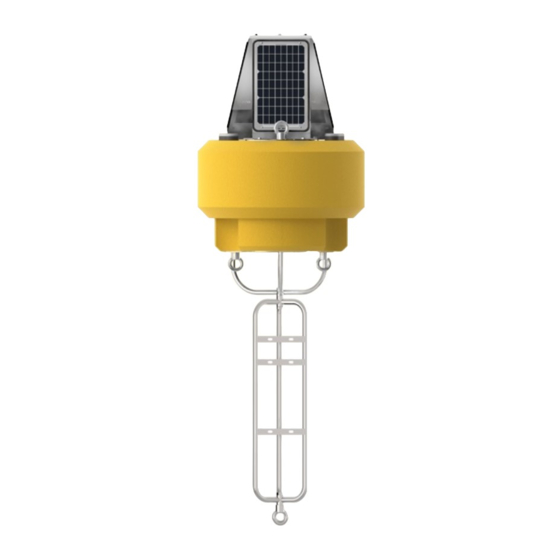
1. General CB-250 Data Buoy Overview The CB-250 data buoy strikes a balance between compact and easy to deploy, yet buoyant and powerful enough to be deployed in larger water bodies including lakes, rivers, coastal waters, harbors, estuaries and other freshwater or marine environments. Like all solar-powered NexSens CB-Series data buoys, it is a highly customizable platform that may be configured with NexSens or user-supplied electronics. - Page 5 For users supplying their own electronics, the CB-250 is delivered as an open platform with empty data well or with battery only. A data well top plate can be supplied in one of three ways: 1. A standard CB-PTL Pass Through Lid for passing of instrument cables through gland fittings 2.
-
Page 6: Key Specifications
Buoy Frame – The skeleton of the buoy is comprised of 316 stainless steel with topside lifting eyes subsurface mooring eyes for single and multi-point moorings. The frame supports attachment of an instrument cage for secure connection of subsurface sensors and additional ballast weight for stability. -
Page 7: Cb-Series Data Buoy Planning & Precautions
Electrical connections – Many NexSens buoy systems utilize UW connectors for connection of power and sensor cables. Data loggers such as the X2-CB have... - Page 8 limited to, working on/near water and lifting of heavy equipment. Important factors to consider for personnel safety are: Use of safety equipment (i.e., life jackets, gloves, steel toed boots, etc.,) Proper lifting and mooring techniques Awareness of on-site and surrounding weather conditions and advisories Despite careful planning, unforeseen situations are always still a possibility.
-
Page 9: Buoy Assembly
CB-Series data buoys are delivered as complete, plug-and-play system packages with a NexSens data logger as the central component of the system. Data Loggers NexSens offers four different data logging systems for buoy deployment, all of which are based on the central processing unit of the X2 environmental data... -
Page 10: Battery Packs
These buoys have a data well for installation of battery packs, and the data logger serves as the top plate to provide a waterproof seal on the data well. NexSens offers two standard types of battery harnesses, which include sealed lead acid (SLA) batteries, solar regulator, mounting bracket and data logger connection cable pigtail (UW-6 connector): CB-A01-2 –... -
Page 11: Installing User-Supplied Electronics In Cb-Series Data Buoys
Installing User-Supplied Electronics in CB-Series Data Buoys NexSens CB-Series data buoys are flexible platforms that allow for use with both NexSens and user- supplied electronics. For those wishing to integrate their electronics, including batteries, data loggers, and modems, several accessories are available to facilitate installation inside the watertight data well located in the center of the buoy. -
Page 12: Securing Data Well Plate
Bulkhead cable assemblies – Ports on a CB-PTL may be interchanged with bulkhead cable assemblies for power, RF signals and sensor data cables. The following options are available: UW6-BULK – 6-pin power cables for connection of batteries, solar panels and regulator RF-BULK –... -
Page 13: Cb-Ptl Bulkhead Connector Assembly Installation
CB-PTL Bulkhead Connector Assembly Installation NexSens CB-Series buoy data wells capped with CB-PTL pass through lids may optionally have UW plug ports replaced with bulkhead cable connector assemblies. Connector Types The CB-PTL comes standard with a UW-6 power bulkhead cable assembly (UW6-BULK) pre-installed. -
Page 14: Power Bulkhead Connector Assembly Wiring
UW-6 Power Bulkhead Connector Assembly Wiring CB-Series Buoys without NexSens integrated electronics will ship with a solar tower and pass-through plate outfitted with a UW-6 power bulkhead connector (UW6-BULK) port. Information regarding the port pinout and different options for wiring power to user-supplied electronics is supplied below. For installation instructions, follow the guide here. -
Page 15: Wiring Options
Orange Solar Connector Jumps to Pin 3 ¹Molex connector is designed to interface with a NexSens CB-A01-2 or CB-A05-x battery harness. If this accessory was not ordered, connector can be cut off to wire to user-supplied components. ²The Red and Black flying lead wires are intended to supply power to user-supplied electronics. -
Page 16: M550 Beacon For Cb-Series Data Buoys
M550 Beacon for CB-Series Data Buoys NexSens M550 Solar Marine Light is a common accessory added to NexSens CB-Series data buoys up to and including the CB-450. Depending on the configuration, it has a 1-3 nautical mile range and is normally delivered with flange mount hardware, yellow color and default 15 flash/minute pattern (Model M550-F-Y). -
Page 17: Operation
Operation The M550 is controlled using an IR programmer that is normally provided with the beacon. programming remote. The IR programmer can be used to perform the following functions: Turn beacon on and off Check the battery pack charge status Change the flash pattern Change the flash intensity... -
Page 18: Cb-Series Data Buoy Instrument Cage Installation
CB-Series Data Buoy Instrument Cage Installation instrument cage attaches to the bottom of CB-Series buoys for water sensor deployments while simultaneously lowering the center of gravity and increasing stability. Model number CAGE is 39″ (99 cm) in length and is normally used with the CB-50, CB-150, CB-250 and CB-450 buoys. -
Page 19: Cb-Cca Anti-Rotation Collar
2. Tighten firmly with a pair of 1-1/8” wrenches such that the lock washer is flattened and the bolt hole is aligned with a notch on the castle nut. Secured cage. 3. Place the cotter pin through the bolt hole and bend the long leg of the pin. Cotter pin with bent leg for security. -
Page 20: Use Of Sacrificial Anodes On Cb-Series Data Buoys
Anodes sourced from NexSens are sized specifically for installation onto buoy frames and instrument cages using a pair of screws provided with the anode. They will typically need to be replaced approximately every 6 months, though this may vary depending on factors such as the temperature and salinity of the saltwater environment. -
Page 21: Cb-Series Data Buoy Instrument Mounts
Miscellaneous Mounts – Other mounting brackets: CB-150/CB-250/CB-450 Instrument Offset Mount Subsurface Mounts Data Logger Mounts – For mounting of NexSens X2-SDL data logger or SBP500 extra/reserve battery packs to instrument cage: X2-SDL Instrument Cage Mount Instrument Deployment Pipes – For instrument installation and topside access using buoy pass through ports: 912M –... - Page 22 918M-PO4 – 8″ diameter for use HydroCycle PO4 sensor on CB-1250 buoy Click for product information instructions for use. Miscellaneous Instrument Mounts – Mounting hardware for some commonly used sensors: Airmar SS510 Sonar Sensor Mount MC-600 Instrument Mooring Clamp Underwater PAR Sensor Mounting Arm YSI EXO Sonde Mooring Clamps Profiling Instrument Mounts –...
-
Page 23: Deployment
Ballast weight may be needed to prevent overturning a CB-series buoy system and ensure stability in the water. The center of gravity of NexSens CB-Series buoys is near the water surface without instruments connected. Therefore, any top-side weight added above the water’s surface (e.g., sensors, sensor mounts) must be appropriately counterbalanced by ballast weight below the surface (e.g.,... -
Page 24: Top-Side Weight
Top-Side Weight Top-side weight is any weight mounted on the buoy above the water surface or the buoys’ center of gravity. Top-side weight located further from the buoys’ center of gravity will cause greater instability of the buoy. For example, suppose a weather sensor is mounted 36″ above the water surface (Figure 2). In that instance, the sensor mount will cause more buoy instability than mounted 24″... -
Page 25: Ballast Weight
If needed, add ½ inch galvanized chain (~2.3lb/ft) to the bottom of the cage, or utilize NexSens 25lb. ballast weight that can be added to the cage in specific applications. -
Page 26: Buoy Ballast Weights
Important: To effectively provide adequate ballast weight, a variety of application-specific criteria (sensor weight and positioning, water level fluctuations, wave and current action, external loading, etc.) must be thoroughly reviewed prior to deployment. NexSens does not endorse using these specific ballast weights for all applications. -
Page 27: Mooring Data Buoys
Mooring Data Buoys This article contains only general information on the available mooring options for NexSens data buoys. Developing an effective mooring strategy requires reviewing various application-specific criteria (water level fluctuations, currents and wave action, debris loads, etc.) before deployment. This document is intended to provide a starting place for mooring design and is by no means comprehensive. - Page 28 1. Catenary Moorings For shallow deployments with minimal wind, wave and current loading, most data buoys utilize catenary moorings. Shallow deployments can be designed with all chain or a combination of heavy bottom chain and light water column chain. Deeper water moorings may need to use a combination of chain and rope. Example catenary mooring deployment with single Example catenary mooring with combination of rope chain for shallow waters.
- Page 29 Small-buoy catenary moorings Additional surface or subsurface floatation may be required for smaller buoyancy buoy applications where the floatation may not be adequate to support the mooring weight. Extra floatation can also free motion for wave measurement applications or offer additional resistance to horizontal loading. Example small-buoy catenary mooring with subsurface Example small-buoy catenary mooring with surface flotation.
- Page 30 Horizontal Loading As wind, wave and current loads increase, the buoy is driven away from the anchor and mooring can be pulled taut resulting in the buoy listing to one side. Damage can result with topside equipment and solar panels becoming submerged. Additional surface or subsurface floatation may be required. Depiction of horizontal loading resulting Force diagram representing external forces acting on in buoy listing to one side.
- Page 31 2. Semi-taut two point moorings For calm, shallow water with limited horizontal loading, semi-taut two point moorings can be utilized. These moorings are useful for suspending sensor lines by pulling the mooring lines free and clear. Rough water, shifting bottom or horizontal loads can tangle two point moorings and lead to chafing and cable failure.
- Page 32 3. Inverse-catenary (S-shape) moorings Inverse-catenary moorings are often referred to as S-shaped moorings. Floats and weights on the mooring lines create an S-shape, which provides spring action in the water column. Waves and water level changes are easily managed. This mooring type is most common on deep water deployments but has utility in shallow rough water applications.
-
Page 33: Troubleshooting And Maintenance
The battery voltage of a CB-Series data buoy can be measured using a DC volt/multimeter on the UW-6 (6-pin) SOLAR port on the data well top plate. This method works for both user-supplied battery systems with CB-PTL pass-through lid and NexSens-supplied CB-A01 and CB-A05 SLA battery systems. - Page 34 A05 12V 28 A-Hr battery commonly equipped in harnesses with one to four A05 units (depending on buoy capacity) on NexSens CB-Series data buoys. A similar process may be followed to replace the A01 batteries of a CB-A01-2 battery harness in a CB-150 buoy.
- Page 35 3. Remove the (8) bolts with lock washers from the buoy plate using a 9/16″ socket wrench. Remove lid to access the buoy data well. 4. Lift the buoy plate off of the data well. Disconnect the 6-pin UW-plug running between the solar regulator and the X2-CB and protect the connectors.
- Page 36 5. Remove the foam coverings to expose the battery harness. Top-view of the solar regulator and battery assembly with protective foam removed. 6. Remove the two nut, lock washer and flat washer pairs securing the regulator bracket to the battery mount posts (threaded rod).
- Page 37 2. [Only for systems with 2 or more batteries] a. Discard any pre-installed hardware on the new battery terminals. Using the original battery terminal bolts and a 10mm socket wrench, tighten the ring terminal cables to the new battery. b. Make sure that the cables point toward the corners of the battery. Always insulate the detached cable leads to prevent short-circuiting the battery during installation.
- Page 38 Hand-tighten solar regulator bracket to the top battery using original mounting hardware. e. Using a 9/16″ socket wrench, tighten down the regulator bracket until it is snug and the lock washers are flattened. Do not over-tighten as this may bow or crack the regulator bracket. f.
- Page 39 UW-6 SOLAR port receptacle pinout for X2-CB data loggers and CB-PTL pass-through lids. 6. Connect the 6-pin solar panel plug to the buoy’s SOLAR port to reapply power to the data logger.
- Page 40 Test a CB-Series Buoy Solar Tower This test process applies to all CB-Series buoy solar towers from the CB-150 up to the CB-1250. Pictures depict a CB-450 tower. 1. Remove the solar tower from the buoy (optional) and verify all panels are clear of debris. 2.
- Page 41 4. Repeat this process two more times, rotating the cardboard/cloth around until all three panels have been isolated and tested. 5. Switch the positive voltmeter lead over to the 10A port and change the setting to measure DC Amps. 6. Measuring again between Pin 2 (V+) and Pin 3 (GND), record the current output of each isolated panel.
- Page 42 Data Buoy Storage Requirements The following practices should be carried out when storing a CB-Series buoy with an X2-CB data logger for an extended period of time: 1. Store the buoy in a dry environment that is kept above freezing. a.
- Page 43 6. Top off the charge of the buoy batteries every 2-3 months by: a. Connecting a NexSens CB-Series Battery Float Charger Kit* b. Reconnecting the solar panel and moving the buoy outdoors into the sun.* NexSens CB-Series Battery Float Charger Kit *While charging, the data logger will be running.
- Page 44 12 months from the date of delivery to the original customer. This warranty is limited to the replacement or repair of such defects, without charge, when the product is returned to NexSens Technology, Inc. Damage due to accidents, misuse, tampering, lack of reasonable care, loss of parts, failure to perform prescribed maintenance, or accidents of nature are not covered.
Need help?
Do you have a question about the CB-250 Data Buoy and is the answer not in the manual?
Questions and answers