
Related Manuals for ELPRO 905U-L


Summary of Contents for ELPRO 905U-L
- Page 1 Installation Manual 905U-L Wireless V e r s i o n 1 . 9 man_905U-L_installation_v1.9.doc...
- Page 2 This warranty is in lieu of and exclusive of all other warranties. This warranty does not indemnify the purchaser of products for any consequential claim for damages or loss of operations or profits and ELPRO is not liable for any consequential damages or loss of operations or profits resulting from the use of these products.
-
Page 3: Table Of Contents
905U-L Wireless I/O Installation Manual Contents Contents __________________________________________________________________ 3 About this document ..........................7 Installing your unit __________________________________________________________ 8 Unit components and connections....................... 9 Transmitter unit ............................... 9 Receiver unit ..............................11 Installing the antenna ......................... 13 Supported antennas ............................13 Radio transmission distances ........................ - Page 4 905U-L Wireless I/O Installation Manual This page intentionally left blank. 905U-L Wireless I/O Page 4 of 40 Version 1.9...
- Page 5 This device must accept any interference received, including interference that may cause undesired operation This device must be operated as supplied by ELPRO Technologies Pty Ltd. Any changes or modifications made to the device without the written consent of ELPRO Technologies Pty Ltd may void the user’s authority to operate the device.
- Page 6 Industry Canada rules. See the label on the unit for the specific Industry Canada certification number and any other certification designations. Any changes or modifications not expressly approved by ELPRO Technologies P/L could void the user’s authority to operate this equipment.
-
Page 7: About This Document
905U-L Wireless I/O Installation Manual About this document This document is the 905U-L Wireless I/O Installation Manual that describes how to install your 905U-L units and contains important information for installing your units with other equipment. Note If your network only contains one transmitter and receiver pair, you should also read the 905U-L QuickStart Guides. -
Page 8: Installing Your Unit
905U-L Wireless I/O Installation Manual Installing your unit This section describes how to install your unit and contains the following sections: For more information, see … Step Description 1 – Read the safety Lets you understand important safety Warning: information information related to your unit. -
Page 9: Unit Components And Connections
Unit components and connections This section shows the components and terminal connections for the transmitter and receiver units. Transmitter unit The 905U-L-T transmitter unit has the following components and terminal connections: Earth Wire Lug underneath Unit 905U-L Wireless I/O Page 9 of 40... - Page 10 905U-L Wireless I/O Installation Manual The front panel contains the following components: SMA antenna connector at top of unit RS232 configuration port Rotary switch for set-point settings The triangle on the rotary switch indicates the current position, for example: Position 0 Position 1 NOTE: To avoid damaging the rotary switch, use a screwdriver to change the position.
-
Page 11: Receiver Unit
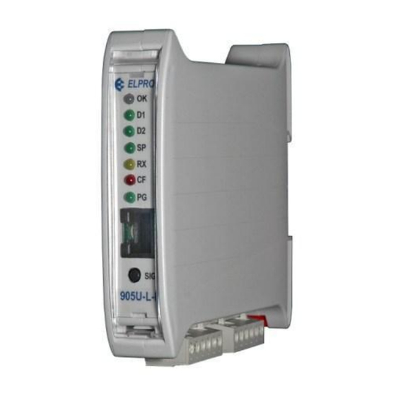
905U-L Wireless I/O Installation Manual Receiver unit Your 905U-L-R unit has the following components and terminal connections: Max. 30VDC 500mA DO 1 For inductive load, use surge diodes DO 2 DO 3 ANALOG OUTPUT Max. analog load 900 ohm DO contacts are rated at 1A, 250VAC... - Page 12 905U-L Wireless I/O Installation Manual The front panel contains the following components: SMA antenna connector at top of unit RS232 configuration port RSSI push-button The LEDs on the front panel indicate the unit status: LED Status Indicates None No power supply.
-
Page 13: Installing The Antenna
905U-L Wireless I/O Installation Manual Installing the antenna This section explains how to install your antenna and contains the following sections: For more information, see … Section Description Supported antennas Details the antennas and cables you can use Supported antennas on page and cables with the units. - Page 14 For example, an SG900-6 antenna with a CC20/900 cable has a net gain of 2dB (i.e. +8 dB – 6 dB) at 900 MHz. The 905U-L-R module has no limitation on antenna gain, as this module does not incorporate a radio transmitter.
-
Page 15: Radio Transmission Distances
1. ELPRO recommends using the 905U-G module as a repeater unit between 905U-L-T and 905U-L-R modules. 2. To use a repeater unit, the 905U-L modules and the repeater module must be configured using the supplied configuration software. The factory default configuration described in the Quick Start Guide cannot use a repeater unit. -
Page 16: Installing And Earthing Antennas
You must connect an antenna to each 905 module using the SMA connector at the top of the enclosure. ELPRO recommends carefully taping the connections between the antenna and coaxial cable to prevent moisture ingress. Moisture ingress in the coaxial cable is a common cause of radio system problem as it greatly increases the radio losses. -
Page 17: Dipole And Collinear Antennas
905U-L Wireless I/O Installation Manual Dipole and collinear antennas This section contains important information for using dipole and collinear antennas. For more information, see the next sections. Dipole antennas Unity gain dipole antennas are commonly used on unlicensed channels. The dipole antenna does not provide any gain, so the power transmitted from the antenna is the same as the power out of the module. - Page 18 905U-L Wireless I/O Installation Manual The following diagrams shows the recommended installation for collinear and dipole antennas: 905U-L Wireless I/O Page 18 of 40 Version 1.9...
-
Page 19: Yagi Antennas
905U-L Wireless I/O Installation Manual Yagi antennas Yagi antennas are directional and have positive gain to the front of the antenna and negative gain in other directions. You can use the gain to: Compensate for coaxial cable loss for transmitter unit; and ... - Page 20 905U-L Wireless I/O Installation Manual The following diagrams shows the recommended installation for collinear and dipole antennas: 905U-L Wireless I/O Page 20 of 40 Version 1.9...
-
Page 21: Installing The Power Supply
905U-L Wireless I/O Installation Manual Installing the power supply The unit works with a 9-30 VDC 0.6 Amp CSA certified Class 2 power supply. For use in Class 1 Div 2 explosive areas, the power supply must be approved for Class 1 Div 2 use. -
Page 22: Inputs And Outputs
905U-L Wireless I/O Installation Manual Inputs and outputs The units have the following inputs and outputs: Input/output 905U-L-T 905U-L-R Description For more information, see … Digital inputs Suitable for Voltage free contact, Digital inputs on NPN transistor, 0-5V signal. page 23. -
Page 23: Digital Inputs
905U-L Wireless I/O Installation Manual Digital inputs The 905U-L-T module provides two digital inputs suitable for: Voltage free contacts – e.g. mechanical switches; or NPN transistor devices – e.g. electronic proximity switches; or 0-5V signals - 2V – 4V Minimum range. -
Page 24: Relay Outputs
905U-L Wireless I/O Installation Manual Relay outputs The 905U-L-R module provides three normally open voltage-free relay contacts rated at 250VAC / 30VDC 1A. You can use these outputs to directly control low-powered equipment or power larger relays for higher-powered equipment. -
Page 25: Status Outputs
905U-L Wireless I/O Installation Manual Status outputs The unit contains the following status outputs: System OK; Setpoint Output; and Communications Failure. Status outputs are FET output to common rated at 30VDC 500 mA. Connect the output circuit to the appropriate Status Output terminal. Each status output circuit is associated with an LED indicator that lights lit when the digital output is active. -
Page 26: Analog Input
You should only connect one end of the cable shield to Earth To connect an analog signal from a PLC or DCS output to an analog input on the 905U-L- T, you must carefully check the internal circuit of the output as different devices use different ways to create an analog signal. - Page 27 905U-L Wireless I/O Installation Manual The following diagrams illustrate different connection methods: Analog Example signal source 2 wire transducer 4 wire transducer Current source output 905U-L Wireless I/O Page 27 of 40 Version 1.9...
- Page 28 905U-L Wireless I/O Installation Manual Analog Example signal source Current sink output 905U-L Wireless I/O Page 28 of 40 Version 1.9...
-
Page 29: Thermocouple Input
905U-L Wireless I/O Installation Manual Thermocouple input The 905U-L-T provides one input suitable for connection to a thermocouple or a millivolt level signal. The module provides linearization tables for J, K and T type thermocouples and also supports other types via a user linearization table. -
Page 30: Pulse Input
905U-L Wireless I/O Installation Manual Pulse input The 905U-L-T module lets you configure the digital inputs as pulse inputs with the following characteristics: Characteristic Value Maximum rate 10 Hz Minimum off time 20 mSec Minimum on time 20 mSec Using this mode, you can map the pulse count to a remote output by transmitting the pulse count to a 905U-G module register or re-generating as a Pulse Output on 905U-1 or Digital Output on a 905-3 unit. -
Page 31: Analog Output
905U-L Wireless I/O Installation Manual Analog output The 905U-L-R module provides a 4 - 20 mA DC analog output for connecting to instrument indicators to display remote analog measurements. The analog output is a current source provided from an internally generated +24V loop supply. - Page 32 905U-L Wireless I/O Installation Manual Connection Example method To single- ended input device 905U-L Wireless I/O Page 32 of 40 Version 1.9...
-
Page 33: Installing And Configuring The Unit
905U-L Wireless I/O Installation Manual Installing and configuring the unit This section describes how to install and configure your unit and contains the following sections: For more information, see … Section Description Installing the unit Describes how to physically install your unit. -
Page 34: Installing The Unit
905U-L Wireless I/O Installation Manual Installing the unit To install the unit: 1. Connect signals to the supplied terminals. 2. Connect the radio antenna. 3. Install DIN rail to mount the module. 4. Clip the module to the DIN rail: You can now configure your unit. -
Page 35: Configuring Your Units
User-defined customized configuration – that lets you set specific information about your network and allows communication with other ELPRO 905 series devices. For more information on setting a user-defined customised configuration, see the User Manual. For more information on setting the factory default configuration, refer to the Quick Start Guide included with your module. -
Page 36: Testing Your Units
For default configuration, check Repeat the procedure to register the receiver is registered with the receiver with the transmitter. the transmitter. For support for other testing issues, please contact ELPRO. 905U-L Wireless I/O Page 36 of 40 Version 1.9... -
Page 37: Unit Specifications
905U-L Wireless I/O Installation Manual Unit specifications This section details the specifications for each unit. Transmitter unit Input/output Number Additional information Dry-contact digital inputs slow-pulsed at 10Hz. Digital inputs All inputs are suitable for voltage free contacts (e.g. mechanical switches) or NPN transistor devices (e.g. -
Page 38: Ancillary Hardware Reference Information
905U-L Wireless I/O Installation Manual Ancillary hardware reference information This section contains reference information about additional hardware components you may need for your unit. RS232 serial cable You can connect the unit to a PC using an RS-232 serial cable to: ... -
Page 39: Index
905U-L Wireless I/O Installation Manual Index 2 wire transducer ............. 27 lightening rod ............16 4 wire transducer ............ 27 lightening strike ............16 AC relays ..............24 line of sight .............. 15 active pulse device ..........See linearization tables ........... 29 active signal device .......... - Page 40 905U-L Wireless I/O Installation Manual specifications ............37 transmitter status outputs ............25 components ............9 surge diverter............16 front panel ............10 surge protection ............16 terminal connections ..........9 surge suppression ........... 16 UV-stabilized tape ........... 16 switches vertical polarization ..........
Need help?
Do you have a question about the 905U-L and is the answer not in the manual?
Questions and answers