Table of Contents
Advertisement
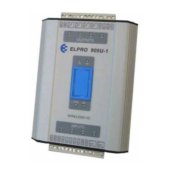
User Manual
905U Wireless I/O Module
105S Serial I/O Module
also includes 105U 5W Wireless I/O range for licensed
frequencies in the 380 – 520 MHz band
For 905U-C, 905U-G, 905U-K and 905U-D products,
refer to separate User Manuals
ELPRO Technologies Pty Ltd, 9/12 Billabong Street, Stafford Q 4053, Australia.
Tel: +61 7 33528600 Fax: +61 7 33528677
Email: sales@elprotech.com
Web: www.elprotech.com
Advertisement
Table of Contents

Related Manuals for ELPRO 905U


Summary of Contents for ELPRO 905U
- Page 1 380 – 520 MHz band For 905U-C, 905U-G, 905U-K and 905U-D products, refer to separate User Manuals ELPRO Technologies Pty Ltd, 9/12 Billabong Street, Stafford Q 4053, Australia. Tel: +61 7 33528600 Fax: +61 7 33528677 Email: sales@elprotech.com...
- Page 2 905U Wireless I/O Module User Manual 105S Serial I/O Module Thank you for your selection of the 905U / 105S module for your I/O needs. We trust it will give you many years of valuable service. ATTENTION! Incorrect termination of supply wires may cause internal damage and will void warranty.
-
Page 3: Man_905-105_2.16
Contents FCC Notice: 905U Wireless I/O Module This user’s manual is for the ELPRO 905U wireless I/O module. This device complies with Part 15.247 of the FCC Rules. Operation is subject to the following two conditions: This device may not cause harmful interference and This device must accept any interference received, including interference that may cause undesired operation. - Page 4 Like all industrial electronic products, ELPRO products can fail in a variety of modes due to misuse, age, or malfunction. We recommend that users and designers design systems using design techniques intended to prevent personal injury or damage during product operation, and provide failure tolerant systems to prevent personal injury or damage in the event of product failure.
- Page 5 ELPRO is not liable for any consequential damages or loss of operations or profits resulting from the use of these products. ELPRO is not liable for damages, losses, costs, injury or harm incurred as a consequence of any representations, warranties or conditions made by ELPRO or its representatives or by any other party, except as expressed solely in this document..
-
Page 6: Table Of Contents
COUNT+ ............................24 2.4.10 RS232 Serial Port ......................25 2.4.11 RS485 Serial Port ......................25 2.4.12 Connecting 105S Modules to 905U Modules ..............26 CHAPTER THREE OPERATION ....................27 ..................27 OWER UP AND ORMAL PERATION 3.1.1 Communications ......................... 27 3.1.2 Change of state conditions .................... - Page 7 ....................... 63 IAGNOSTICS HART ......................64 UNCTIONS 6.2.1 Input to Output Reflection (905U-1/105S-1 only) ............. 64 6.2.2 Radio Testing using Tone Reversals (105U/905U modules only) ........64 6.2.3 Diagnostics menu ........................ 64 6.2.4 Comms Logging ........................71 ......................73 ADIO ESTING CHAPTER SEVEN WARRANTY &...
-
Page 8: Chapter One Introduction
Telemetry is the transmission of signals over a long distance via a medium such as radio or twisted-pair wire. Although the 905U/105S is intended to be simple in its application, it also provides many sophisticated features. This manual should be read carefully to ensure that the modules are configured and installed to give reliable performance. - Page 9 The 905U radio has been designed to meet the requirements of unlicensed operation for remote monitoring and control of equipment. That is, a radio licence is not required for the 905U modules in many countries. See Chapter Five Specifications for details. The 105U radio is suitable for fixed frequency licensed channels in the 380-520MHz band - that is, a radio license is required to use the 105U products, but not the 905U products.
- Page 10 Systems with a 905U-C or 905U-G module and host device can have more than 95 radio modules. Modules can be used as repeaters to re-transmit messages on to the destination module. Repeaters can repeat messages on the radio channel, or from the radio channel to the serial channel (and serial to radio).
-
Page 11: Chapter Two Installation
Antenna Installation (905U & 105U units only) The 905U module will operate reliably over large distances. The distance which may be reliably achieved will vary with each application - depending on the type and location of antennas, the degree of radio interference, and obstructions (such as hills or trees) to the radio path. Typical reliable... - Page 12 User Manual 105S Serial I/O Module the antenna is a larger obstruction than a group of trees further away from the antenna. The 905U modules provide a test feature which displays the radio signal strength. Line-of-sight paths are only necessary to obtain the maximum range.
-
Page 13: Dipole And Collinear Antennas
For example, a 6 element Yagi with 70 feet (20 metres) of Cellfoil has a net gain of 4dB (10dB – 6dB). For information on antennas and cables for the 105U licensed products, please refer to ELPRO or an authorized distributor. - Page 14 905U Wireless I/O Module User Manual 105S Serial I/O Module The Yagi gain also acts on the receiver, so adding Yagi antennas at both ends of a link provides a double improvement. Yagi antennas are directional. That is, they have positive gain to the front of the antenna, but negative gain in other directions.
-
Page 15: Power Supply
Installation Power Supply The 905U/105S power supply is a switch-mode design which will accept either AC or DC supply. The module may also be powered from a solar panel without an external solar regulator. The module accepts supply voltages in the following ranges : 12 - 24 volts AC RMS or 15 - 30 volts DC at the “supply”... -
Page 16: Solar Supply
The Module load depends on the I/O connected and can be calculated as follows: Module Load(mA) = (85 for 105U/905U or 45 for 105S) + (10 x No. of active DI’s) + (25 x No. of active DO’s) + (2 x Analog loop load). -
Page 17: Multiple Modules
For example, assume there is a 905U-1 module and a 105S-1 module at the same location. The total I/O at the location is 3 analog inputs, 6 digital inputs and 4 digital outputs. The total load will be :-... -
Page 18: Regulated Supply
105S Serial I/O Module 2.3.5 24V Regulated Supply Each module provides a 24V DC regulated supply for analog loop power, except for 905U-4/105S-4. The supply is rated at 150mA, and should only be used for powering analog loops. Input / Output 2.4.1 Digital Inputs (905-1, 905-2 and 905-4) -
Page 19: Digital Outputs (905-2, 905-3 And 905-4)
Load Max 30VDC 0.5A 905U Digital outputs may be configured to individually turn off if no command message is received to that output for a certain period. This feature provides an intelligent watch dog for each output, so that a communications failure at a transmitting site causes the output to revert to a known state. - Page 20 To connect an AI on the 905U to an analog signal from a PLC or DCS output, check the internal circuit of the output carefully as different devices use different ways to create an analog signal. The following diagram shows two ways of connecting.
-
Page 21: Analog Outputs (905-1 And 905-3)
If connecting to an external device such as an electronic indicator, recorder or PLC / DCS input, the loop can be powered be either the 905U or the device. Externally powered loops to 27 VDC may be connected by connecting the output between the "AO” terminal (positive) and the "COM" terminal (negative). - Page 22 905U Wireless I/O Module User Manual 105S Serial I/O Module +24V AO 1 DEVICE 905U Connecting to a floating input device, powered from the 905U Note: COM on 905U is connected +24V ground/earth. the external power AO 1 supply cannot be...
-
Page 23: Pulse Input (905-1)
Active pulse signals can be connected directly provided the peak voltage is between 3.5–13V and the low voltage is less than 1.5V. Note that the 905U will ground the negative of the pulse signal. If the voltages are not compatible, use a solid state relay to isolate the two devices. -
Page 24: Pulse Output (905-1)
Some devices such as PLC counter modules power the pulse loop. For these devices, connect to the PO and COM terminals of the 905U. The COM terminal will connect a ground/earth to the external device. If this is not suitable, use a solid state relay to isolate the external device. -
Page 25: Rs232 Serial Port
RS485 is disconnected before attempting to use the RS232 port. Communication is via standard RS-232 signals. The 905U/105S is configured as DCE equipment with the pin-out detailed below. The serial port communicates at a baud rate of 9600 baud, 8 bits, no parity, one stop bit. An... -
Page 26: Connecting 105S Modules To 905U Modules
105S modules connect to a 905U via the RS485 port on each module - refer to section 2.4.11. Up to 31 x 105S modules can be connected to a 905U module. This number is reduced for 105S-3 and –4 modules, as these modules use two unit addresses (refer to chapter 4 of this manual). -
Page 27: Chapter Three Operation
3.1.1 Communications Before each transmission, the 905U radio will “listen-before-transmit” to make sure that another module is not already transmitting - if there is another transmission, the 905U will wait until the man_905-105_2.16 Page 27... - Page 28 User Manual 105S Serial I/O Module transmission is complete. When the 905U transmits, it will wait for a return “acknowledgement” message from the destination module, indicating a successful message. If transmissions are not successful (radio or serial), then the module will re-try up to four times at random intervals to transmit the message.
-
Page 29: Change Of State Conditions
3 seconds, however a 105U will take 10 – 20 seconds. Repeaters can be used in a system to increase range. Each 905U unit can be configured to act as a repeater. When configuring an input to be mapped to an output, the communications path to the output unit, including the repeater addresses is specified. - Page 30 905U Wireless I/O Module User Manual 105S Serial I/O Module Analog Change-of-state A "change-of-state" for an analog input, battery voltage or pulse input rate is a change in value of the signal of 3% (configurable) since the last transmission. Note that the sensitivity of 3% refers to 3% of the analog range, not 3% of the instantaneous analog value.
- Page 31 The default period is 1 minute and is configurable. The absolute pulse count is transmitted. If the PI is transmitted to a PO on a 905U/105S module, then the pulse outputs are re-created from the accumulated pulse count. Rollovers of the pulse count thru zero are catered for.
-
Page 32: Analog Set-Points
905U Wireless I/O Module User Manual 105S Serial I/O Module are treated as an “internal” analog input and are configured with analog sensitivities for change-of- state transmissions. The maximum pulse rate corresponding to 20mA output may be configured by the user. -
Page 33: Resetting Outputs
If there are other users on the radio channel, then this peak figure will also decrease. Dual Band Operation The 905U radio band is split into two sub-bands, 902-915 MHz and 915 – 928 MHz . In America and man_905-105_2.16... -
Page 34: Radio Path Reliability
Canada, the 905U uses both sub-bands - but in other countries, only the high sub-band. In America and Canada, it is possible to restrict the frequency hopping of the 905U to only the high or low band. If there are many 905U systems in the same area, this technique will help to separate systems to avoid radio interference. -
Page 35: Indicating A Communications Problem
Chapter Three Operation receive an update or change message every 10 minutes, and it has not received a message within this time, then some form of failure is likely. If the output is controlling some machinery, then it is good design to switch off this equipment until communications has been re-established. The modules provide a “drop outputs on comms fail”... -
Page 36: Testing And Commissioning
2. Mal-operation, or operating when not requested. This problem occurs when an output is “triggered” by the wrong radio device. The 905U modules use frequency encoding and a very secure addressing system to ensure this does not occur. An additional security level using data encryption can also be selected. -
Page 37: Chapter Four Configuration
The four different I/O versions in the range can be used together in the same system. 905U-C and 905U-G modules can also be part of a system. Inputs to one product type can be transmitted to outputs of another product type. For example, an analog input to a ”-2” may be transmitted to an analog output of a ”-1”... -
Page 38: Easy Configuration Using Default Settings
905U Wireless I/O Module User Manual 105S Serial I/O Module Easy Configuration Using Default Settings If your application requires only a single pair of modules, communicating via radio or serial link, default settings may satisfy your needs. If so, no configuration is required. Essentially, all inputs at Module A are reflected at the corresponding outputs at Module B. - Page 39 Chapter Four Configuration For “-2” and “-3” modules, the default configuration is as follows :- Note that there is no default configuration for the “-4” modules. The following table details the default values for User Options: Option Factory Set Value Update transmissions Every 10 minutes Analog Change-of-state sensitivity...
-
Page 40: Configuration Software
AI2 → I/O Reg 1036 at 10 via 7 This mapping links AI2 on a 905U module to I/O Register 1036 in a 905U-C with address 10. Module #7 is used as a repeater. The host device connected to the 905U-C can read the I/O register. - Page 41 Chapter Four Configuration setup stage. The Initial screen will appear. The configuration is performed for a complete system. The necessary configuration stages are : select system name and system address select individual units and unit addresses configure I/O mappings for each unit ...
- Page 42 105U-1, 105S-1 or a 905U-1. The program will ask to select the unit address and will display the list of available addresses for you to select. For 905U modules, select an address between 1 and 95. For 105S modules, select an address between 96 and 127.
- Page 43 Chapter Four Configuration Configuring an individual module Double-click on a unit shown on the left-hand menu. The configuration options for each unit will appear. We recommend that you configure I/O mappings first, and then other options. Select “Mappings” and the following screen appears. There are three types of mappings: •...
- Page 44 905U Wireless I/O Module User Manual 105S Serial I/O Module I/O Mapping To enter an I/O mapping, select “New I/O Mapping”. 1. The I/O mapping display will show all inputs at the selected module - both physical inputs and internal inputs. Select the input to be mapped.
- Page 45 DIO 4 DIO 12 6. If you select a 905U-G as the destination module, you will be asked to select a I/O Register as the destination “output”. Note that the grey-shaded I/O registers have already been allocated. 7. Select any intermediate repeater units needed to reach the destination address (entered in order of nearest to furthermost repeater).
- Page 46 905U Wireless I/O Module User Manual 105S Serial I/O Module When a unit is first turned on, its outputs will not be set until it receives update messages from other units in the system. To ensure that outputs are set as soon as possible after start-up the unit may be configured to “Poll”...
- Page 47 Chapter Four Configuration Debounce Configuration Debounce is the time which input must stay stable before the module decides that a change of state has occurred. If a digital input changes (say 0 → changes again (1 → 0) in less than debounce time,...
- Page 48 905U Wireless I/O Module User Manual 105S Serial I/O Module each field. The display also shows the maximum and minimum values. For the -1, -2 and –3 modules, the maximum update time is 16 minutes, however the update time for -4 inputs can be up to 5 days.
- Page 49 Chapter Four Configuration Analog Sensitivity Configuration The analog sensitivity is the change required in an analog input before a “Change Of State” is detected, and the new analog value is transmitted. For input signals which vary widely over a short period of time or have a normal oscillation, the analog sensitivity should be set to an appropriately large value.
- Page 50 905U Wireless I/O Module User Manual 105S Serial I/O Module PI1 of the -2 and -4 modules normally count up to 100Hz (as for the other PI’s), however configured to count up 1000Hz. This configuration actually divides the input count...
- Page 51 Chapter Four Configuration Pulse Output Update Time Configuration The pulse output update time is the time period over which pulses are output after a PI update is received. It should be configured to correspond to the pulse input update time for the corresponding pulse input.
-
Page 52: Loading Configuration From A Module
If security has been enabled for the system, please read section 4.3.7. If you are adding additional mappings to a 905U-C or 905U-G module, then you need to change the archived configuration files first so you can download the modified configuration details into the 905U-C or 905U-G 4.3.5 Modifying and Archiving Configuration Files... -
Page 53: Print Options
Chapter Four Configuration recommend that all system additions and changes be made to the archived configuration files first, and then downloaded to the module/s. This ensures that the archived files are always maintained and accurate. If you modify the configuration of a module by uploading and then downloading, then the module configuration will be different then the archived files. - Page 54 These security options provide a high level of security, but no data-security system can provide “100% protection”. But it does make it very difficult for someone to interfere with the 905U system - difficult to the point where there would be many easier alternate ways to cause malicious damage.
-
Page 55: Using 105S Modules
I/O expansion for 905U modules. As the 105S modules are connected by RS485, the 105S modules can be separated from the 905U modules by some distance. There can be up to 32 addresses on the one RS485 multi-drop link. Note that each –3 and –4 module takes up 2 addresses. For example, you could have up to 32 modules sharing a multi-drop link if they are all –1 or -2 modules - if they are all... - Page 56 Example 2 - Mapping to a remote 905U. In this example, a 105S-2 is connected to 905U-1#8. DI1 is mapped to a remote 905U-C module. The 905U that is connected to the 105S module acts as a repeater - a serial-to-radio repeater.
- Page 57 Chapter Four Configuration Example 3 - Mapping to another 105S which is connected to a different 905U In this example, both 905U modules act as repeaters. 905U-1 The first is a “serial-to- 905U-1 radio” repeater second is a “radio-to-serial” repeater.
-
Page 58: Chapter Five Specifications
905U Wireless I/O Module User Manual 105S Serial I/O Module Chapter Five SPECIFICATIONS General 905U Radio standards FCC Part 15A, Part 15.247 902 – 928 MHz, 1W 105U Radio standards FCC Part 90, Part 15, RSS- 380 – 520 MHz, 12.5 / 25KHz, 0.5 – 5W... - Page 59 Chapter Five Specifications Mains fail status Monitored Can be transmitted to remote modules Battery voltage Monitored As above Radio Transceiver (905U) Spread spectrum Frequency hopping Frequency USA/Canada 902 – 928 MHz Australia 915 – 928 MHz New Zealand 922 – 928 MHz...
- Page 60 905U Wireless I/O Module User Manual 105S Serial I/O Module Inputs and Outputs Digital Inputs 905U/105S-1 Four Opto-isolated (5000V)inputs, suitable for voltage free contacts or NPN transistor, contact wetting current 5mA, input debounce 905U/105S-2 Four 0.5 second 905U/105S-3 None For –4 modules, as above, but with 3000V...
-
Page 61: Dimensioned Drawing
Chapter Five Specifications Network Configurations Communications via radio Up to 95 radio units with up to 32 serial units or RS485 or network of off each radio unit both User Configuration Any input to any output in RS232 PC or laptop system Diagnostics On board diagnostics... - Page 62 905U Wireless I/O Module User Manual 105S Serial I/O Module OUTPUTS ELPRO xxxx-x (1.4”) (7.5”) 165 mm 60 mm (6.5”) (2.4”) RADIO TELEMETRY MODULE INPUTS (5.1”) 82.5 mm (3.25”) 55 mm (2.16”) 62 mm (2.45”) Page 62 © January 2011...
-
Page 63: Chapter Six Troubleshooting
Chapter Six Troubleshooting Chapter Six TROUBLESHOOTING Diagnostics Chart INDICATOR CONDITION MEANING • Battery Voltage low OK LED OFF Continuously • CPU failure • +24V supply failure/overload • Normal Operation OK LED ON Continuously • Supply available from SUP1/SUP2 PWR LED ON Continuously •... -
Page 64: Self Test Functions
If a module does not pass its self test function, then it should be returned to an authorised service agent for attention 6.2.2 Radio Testing using Tone Reversals (105U/905U modules only) This function allows the unit to be configured to continuously transmit a sequence of alternate zeros and ones on the radio. - Page 65 Chapter Six Troubleshooting The diagnostics functions can be accessed from the E Series Config software - the same software package used to configure the modules. Connect the laptop or PC to the module using a configuration RS232 cable. Either open the archived project containing the module, or start a New Project and select “Load a New Unit”...
- Page 66 After the diagnostics session is over, force the module to restart, then select “Stop Terminal”, then “Close”. Inputs This option provides a dynamic display of the status of all of the inputs in the 905U, both internal and external. Page 66...
- Page 67 Chapter Six Troubleshooting 905U-1/105S-1 Modules 1234MLS P CNT AI1 PRATE VBATT 0101001 00F6 C000 4000 8000 9C00 The first 7 values (1234MLS) each represent a single digital input. A ‘1’ indicates that that input is ON, and a ‘0’ indicates that the corresponding input is OFF. "1234" represents the four physical digital inputs, DI1 to DI4.
- Page 68 905U Wireless I/O Module User Manual 105S Serial I/O Module 16 volts. A quicker method is use the calculation: Battery voltage (volts) = ½ I + 6, where I is the mA value determined from the above table using VBATT. For example, a value of VBATT of A000 gives an I value of 16mA from the above table.
- Page 69 Chapter Six Troubleshooting below) to check the path between two units. Comms This function allows monitoring of all messages transmitted and received over the radio. A better comms display function is available using the “Comms Logging” feature in the configuration software - refer to section 6.2.4.
- Page 70 905U Wireless I/O Module User Manual 105S Serial I/O Module of the switches of which there are two sets of eight, with an “Enter” button located to the right of the pair. the display indicates the current switch settings with the digit ‘1’ corresponding to ‘On’ and the digit ‘O’...
-
Page 71: Comms Logging
Chapter Six Troubleshooting example, if the radio test is done during winter and the radio path is through trees without leaves, then another 10dB of margin should be allowed for to cover summer conditions when the trees have leaves. When using directional antennas (i.e. YAGI antennas) this feature may be used to peak the received signal level. - Page 72 905U Wireless I/O Module User Manual 105S Serial I/O Module If you select any message line with the mouse, information about the message will be displayed at the bottom of the screen - the system address, RSSI and CRC (error-check) status. The “text box” at the bottom middle of the screen decodes the message - that is, it decodes the message to display I/O channel and value.
-
Page 73: Radio Path Testing
Chapter Six Troubleshooting Radio Path Testing To carry out a radio path test, you will need two 905U modules. One module will be “fixed” and the other “mobile”. Both units will need power supplies and antennas. The power supply for the mobile unit is normally a 12V battery, but make sure that the battery is fully charged - batteries with low voltage will lead to low radio power which will affect the test result. - Page 74 2. Change one or both antennas to a higher gain if regulations allow. 3. Use a shorter coaxial cable between the antenna and the 905U.(this may involve moving 905U nearer to antenna mounting), or use a different coaxial cable with lower loss.
-
Page 75: Chapter Seven Warranty & Service
ELPRO is not liable for any consequential damages or loss of operations or profits resulting from the use of these products. ELPRO is not liable for damages, losses, costs, injury or harm incurred as a consequence of any representations, warranties or conditions made by ELPRO or its representatives or by any other party, except as expressed solely in this document.. -
Page 76: Appendix Asystem Example
A 905U-1 module is installed at the pump station (with address 1) and a 905U-2 module is installed at the tank station (with address 2). Because the signal cable to the control station does not have enough cores for all of the signals required, the signal cable is used as a RS485 cable and a 105S-3 module is installed at the control station (with address 96). - Page 77 There was an existing electrical enclosure at the pump station, and the 905U module was installed inside this enclosure. The module was powered from a 24VDC supply with a 2 Amp Hour sealed battery as backup.
- Page 78 905U Wireless I/O Module User Manual 105S Serial I/O Module Tank Station Configuration The 905U-2 module has the following configuration :- Note the following points in the configuration : • #1 is a repeater for communications between #2 and #96 •...
- Page 79 "divide by 10" (for 1000 Hz pulse signals). • AIN1 (the level transducer) is mapped to AO1 at the 905U-3. The analog debounce has been set to 2 sec. This is because of concern of wave action on the surface of the tank causing un-necessary change transmissions.
- Page 80 905U Wireless I/O Module User Manual 105S Serial I/O Module Note the following points in the configuration: • Note that no repeater address is necessary between #1 and #96. • DIN2 (pump running signal) has two mappings - a mapping to DO1 at #2 (tank station) and DO2 at #96 (control station).
- Page 81 Appendix B Terminal Layouts • PO 3 has been configured as a PO. Its pulse output update time is the same as the PI update time at the remote module (both have been left at their default value of 1 minute). •...
-
Page 82: Appendix B Terminal Layouts
905U Wireless I/O Module User Manual 105S Serial I/O Module Appendix B TERMINAL LAYOUTS WIRING DRAWING - 105U-1, 905U-1 105S-1 OUTPUTS ELPRO xxxx-1 INPUTS Page 82 © January 2011... - Page 83 Appendix B Terminal Layouts WIRING DRAWING - 105U-2, 905U-2 105S-2 OUTPUT ELPRO xxxx-2 INPUTS man_905-105_2.16 Page 83...
- Page 84 905U Wireless I/O Module User Manual 105S Serial I/O Module WIRING DRAWING - 105U-3, 905U-3, 105S-3 OUTPUTS ELPRO xxxx-3 OUTPUTS Page 84 © January 2011...
- Page 85 Appendix B Terminal Layouts WIRING DRAWING - 105U-4, 905U-4, 105S-4 OUTPUTS ELPRO xxxx-4 INPUTS man_905-105_2.16 Page 85...
Need help?
Do you have a question about the 905U and is the answer not in the manual?
Questions and answers