Table of Contents
Advertisement
Quick Links
Advertisement
Table of Contents

Related Manuals for Tempest MVU-48


Summary of Contents for Tempest MVU-48
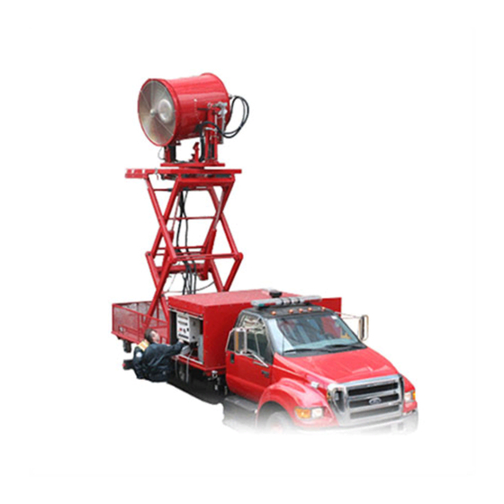
- Page 1 48” Mobile Ventilation Unit Operation Manual For Additional Information, contact Tempest Technology Corporation 4708 N. Blythe Ave. Fresno, CA 93722 Tel. +559-277-7577 Fax. +559-277-7579 Email response@tempest.us.com Internet www.tempest.us.com...
-
Page 2: Table Of Contents
Starting and Stopping Instructions ……………………………..…….. 26 MVU Maintenance Schedule ……………………………………..…… 27 MVU Troubleshooting Guide ………………………………………….. 29 Spare Parts List ……………………………………….………………….31 Electrical Wiring Diagrams …………………………….………………. 32 Hydraulic System Diagrams …………………………….…………….. 39 Murphy Display and Diagnostic Module …………….……………….. 43 Copyright 2004, Tempest Technology Corporation... -
Page 3: General Information
Tempest Technology, Inc. Technical Information: The information contained in this operation manual, images, and data correspond to the product as of the date it was written. The Tempest MVU is in a continuous cycle development improvement. We reserve the right to make any changes or improvements that we consider to be appropriate. - Page 4 Before you put the MVU into service, take the time to thoroughly read this manual to familiarize yourself with it. Diesel Engine Operation Operation and maintenance of the diesel engine: see engine manufacturer’s manual. Copyright 2005, Tempest Technology Corporation...
- Page 5 If your device should be equipped with different equipment that is not itemized or described in these operating instructions, please notify Tempest Technology. You will be informed by our technical staff about the correct operation and maintenance.
- Page 6 The MVU may only be serviced by personnel who have been properly trained in the hydraulic and operating systems maintenance. Ongoing training with the MVU as well as education through specialty training will guarantee proper performance and reliability. Copyright 2005, Tempest Technology Corporation...
-
Page 7: Warning Signs And Symbols
Injury Danger! Special statement to prevent property damage and promote general cautious measures. ATTENTION! Statement with respect to the economic use of the device as well as additional information maintenance maintenance work. Environmental Protection Copyright 2005, Tempest Technology Corporation... - Page 8 The diesel engine which powers the Exhaust hydraulic system emits poisonous Fumes exhaust fumes! Exhaust fumes can cause severe health damage! Do not operate the ventilator in a closed, unventilated room! Dangerous exposure to carbon monoxide (CO) can result! Copyright 2005, Tempest Technology Corporation...
- Page 9 Only operate the ventilator if all Protection protection devices are in place! Arrangement Before removing the protection devices, disengage the motor and drives as well as disconnect the ignition power! Copyright 2005, Tempest Technology Corporation...
-
Page 10: Safety Measures
Measures Maintenance and service should only be Maintenance conducted by persons who are properly trained and know the safety precautions and accident-prevention procedures. Disengage the motor and drives as well as disconnect the ignition power! Copyright 2005, Tempest Technology Corporation... - Page 11 No metal objects should be placed on the battery – this creates the danger of a short circuit! Use only original power rated batteries! If too strong a battery is used, the electrical system can be damaged! Copyright 2005, Tempest Technology Corporation...
- Page 12 ¨ Wear eye protection ¨ Do not tilt the battery, acid can spill out of the opening. unloaded battery freeze, therefore store it where it will not freeze! Properly recycle old batteries in an Disposal authorized recycling facility. Copyright 2005, Tempest Technology Corporation...
- Page 13 TEMPEST MVU Operation Manual Spare parts During maintenance and replacement of parts, only original parts from Tempest Technology, Inc. may be used! The use of spare parts and accessories that do not come from Tempest Technology, Inc. or are not tested and...
- Page 14 TEMPEST MVU Operation Manual Maintenance problems occur during Support and maintenance service Service ventilator, please contact: Tempest Technology, Inc. 4708 N. Blythe Ave. Fresno, CA 93722, USA Tel: +559-277-7577 Fax: +559-277-7579 Copyright 2005, Tempest Technology Corporation...
-
Page 15: 48" Mvu Specifications
Volume of air: 80,000 CFM (130,000 Effective CFM) 380,000 CFM nominal open airflow Velocity of air stream at outlet: 70 MPH Fan Adjustment Scissors Lift: 118” max lift Tilt up: 45° Tilt down: 45° Rotation: 360° continuous Copyright 2005, Tempest Technology Corporation... - Page 16 § Lowering System raise/lower Remote Control: § Portable control box with 20 foot cable § Engine/fan RPM § Fan, start/stop § Tilt, up/down § Rotation, left/right § Scissors, up/down § Lowering system raise/lower § Emergency shut-down switch Copyright 2005, Tempest Technology Corporation...
- Page 17 Hydraulic lowering mechanism for the fan unit to reduce the overall height of the unit by 7". Can reduce the height to legal limits for highway transportation when unit is mounted on a truck with a tall platform. Copyright 2005, Tempest Technology Corporation...
-
Page 18: Mvu Misting System
100 feet. The finely dispersed droplets of the water vapor absorbs heat, inert fumes, and wash-down hazardous vapors. Flow rates may be decreased or increased if so desired. The heat absorption capacity amounts to 25,000 kJ/sec. Copyright 2005, Tempest Technology Corporation... -
Page 19: Control Panel Features And Operation
Hydraulic Oil Temp Warning Engine Ignition Lamp Test Emergency Stop Engine Water Temp Compartment Lights Engine Oil Pressure Engine Voltage Meter Engine Display/Diagnostic Engine Fuel Level Engine Tachometer Fan Pump Pressure Yoke Raise/Lower Aux Pump Pressure Copyright 2005, Tempest Technology Corporation... - Page 20 Wait until the temperature cools. The motor can then be turned on again. The hydraulic cooling fan starts when the oil temperature reaches 145 degrees Fahrenheit. 8 Lamp Test for To test that the warning lamps are functioning properly. 4, 5, 6, 7 Lamps Copyright 2005, Tempest Technology Corporation...
- Page 21 UP. To reduce fan speed, jog FAN SPEED switch DOWN. The maximum allowable fan speed is 1,150 RPM. This maximum number of revolutions is electronically limited and corresponds 1,450 engine RPM. WARNING: Exceeding the maximum allowable fan RPM can lead to blade failure! Copyright 2005, Tempest Technology Corporation...
- Page 22 The power output is 24V. Normal operating range is Voltage, 24v 24-26 volts. 24 Engine Fuel Indicates the level of the fuel tank. The capacity of the tank is 55 Level gallons. Copyright 2005, Tempest Technology Corporation...
- Page 23 3,000 psi at maximum RPM. 26 Aux Pump Shows the pressure in the auxiliary pump. Pressure should be 2,000 Pressure psi during tilting, 800-1,350 psi during lifting, and 2,000 psi during lowering Copyright 2005, Tempest Technology Corporation...
-
Page 24: Remote Control System
3 Fan Unit Lift Up / Down 3 Yoke Raise Raise / Lower 4 Fan Unit Rotate Right / Left 5 Fan Speed Up = Faster / Down = Slower 6 Emergency Shut-Down Shuts Down Diesel Engine Copyright 2005, Tempest Technology Corporation... -
Page 25: Ventilator Bracket And Lowering System Operation
Yoke in Nested Position Yoke in Raised Position The MVU features a hydraulically-controlled lowering system that reduces the overall height of the MVU for transportation. Before operating the MVU, the yoke is raised to the operating height. Copyright 2005, Tempest Technology Corporation... -
Page 26: Starting And Stopping Instructions
1. To turn fan on, turn FAN switch to START. 2. To increase fan speed, jog FAN SPEED switch to RAISE. 3. To reduce fan speed, jog FAN SPEED switch to LOWER. 4. To turn fan off, turn FAN switch to STOP. Copyright 2005, Tempest Technology Corporation... -
Page 27: Mvu Maintenance Schedule
Prior to Each Operation 1. Check engine oil level. 2. Check engine water level. 3. Check battery. 4. Check hydraulic oil level. 5. Inspect hoses and fittings for leaks or abrasions. After 500 Hours or 6 Months Copyright 2005, Tempest Technology Corporation... - Page 28 2. Check fan belt for wear or cracks and replace if damaged. 3. Drain and flush cooling system. 4. Clean radiator core of obstructions. 5. Check radiator cooling hoses, replace if damaged or leaking. 6. Check radiator cap for pressure holding. Copyright 2005, Tempest Technology Corporation...
-
Page 29: Mvu Troubleshooting Guide
TEMPEST MVU Operation Manual Copyright 2005, Tempest Technology Corporation... - Page 30 Troubleshooting Guide Follow these instructions if any of the systems on the MVU are not working properly. If the problem cannot be solved or determined, please contact Tempest at +559-277-7577. The Tempest offices are open from 8:00am to 5:00pm Pacific Standard Time, Monday through Friday.
- Page 31 2. Relay malfunction. Jump Starting the MVU: If the battery of the MVU system is dead, it is possible to jump start the MVU using jumper cables. Only hook to one battery and not across the system Copyright 2005, Tempest Technology Corporation...
-
Page 32: Spare Parts List
Control Panel Switches 582-001 3 Position Selector Switch 582-002 2 Position Selector Switch 582-003 Switch Keyed Selector Start 582-004 3 Position Switch Green Light Control Panel Relays 582-005 4PDT Relay & Socket 582-006 DPDT Relay Copyright 2005, Tempest Technology Corporation... - Page 33 TEMPEST MVU Operation Manual Copyright 2005, Tempest Technology Corporation...
- Page 34 TEMPEST MVU Operation Manual Copyright 2005, Tempest Technology Corporation...
- Page 35 TEMPEST MVU Operation Manual Copyright 2005, Tempest Technology Corporation...
- Page 36 TEMPEST MVU Operation Manual Copyright 2005, Tempest Technology Corporation...
- Page 37 TEMPEST MVU Operation Manual Copyright 2005, Tempest Technology Corporation...
- Page 38 TEMPEST MVU Operation Manual Copyright 2005, Tempest Technology Corporation...
-
Page 39: Hydraulic System Diagrams
TEMPEST MVU Operation Manual Copyright 2005, Tempest Technology Corporation... - Page 40 TEMPEST MVU Operation Manual Copyright 2005, Tempest Technology Corporation...
- Page 41 TEMPEST MVU Operation Manual Copyright 2005, Tempest Technology Corporation...
- Page 42 TEMPEST MVU Operation Manual Copyright 2005, Tempest Technology Corporation...
-
Page 43: Murphy Display And Diagnostic Module
TEMPEST MVU Operation Manual Copyright 2005, Tempest Technology Corporation...
Need help?
Do you have a question about the MVU-48 and is the answer not in the manual?
Questions and answers