
Subscribe to Our Youtube Channel
Related Manuals for Alfa Network Optigo FMC


Summary of Contents for Alfa Network Optigo FMC
- Page 1 Optigo FMC Instruction manual • Product description • Product labels • Unpacking & lifting • Installation • Maintenance • Spare parts ORIGINAL INSTRUCTIONS 31369765EN-07...
-
Page 3: Table Of Contents
Index Important information ......................5 Disclaimer ..........................5 Intended use ..........................5 Where to find product information .................... 5 Warning symbols ........................5 Health, safety and hygiene ....................... 6 Checks at delivery ........................6 Return of unused heat exchangers ..................6 Guarantee .......................... - Page 4 7.11 Fan shroud heater (optional) ....................41 7.12 Thermostatic expansion valve (optional) ................42 Residual risks ........................43 Troubleshooting ........................44 Spare parts ..........................45 10.1 Spare parts (F27MC models) ....................45 10.2 Spare parts (F31MC and F35MC models) ................46 31369765EN-07 Alfa LU-VE is a trademark registered and owned by LU-VE Group.
-
Page 5: Important Information
Important information Disclaimer This Instruction Manual applies to all Optigo FMC air cooler products. Manual must be carefully examined and instructions should be followed up at all times. Alfa LU-VE does not accept liability for any damage resulting from non-compliance to the instruc- tions as given in the manuals and order-related documents. -
Page 6: Health, Safety And Hygiene
Health, safety and hygiene Ensure that the following guidelines are observed: • All work on the equipment must be carried out by trained personnel. • The electrical supply is suitable for the equipment supplied. • Refrigerant, temperature and pressure must agree with the data on the product label of the relevant heat exchanger. -
Page 7: Product Description
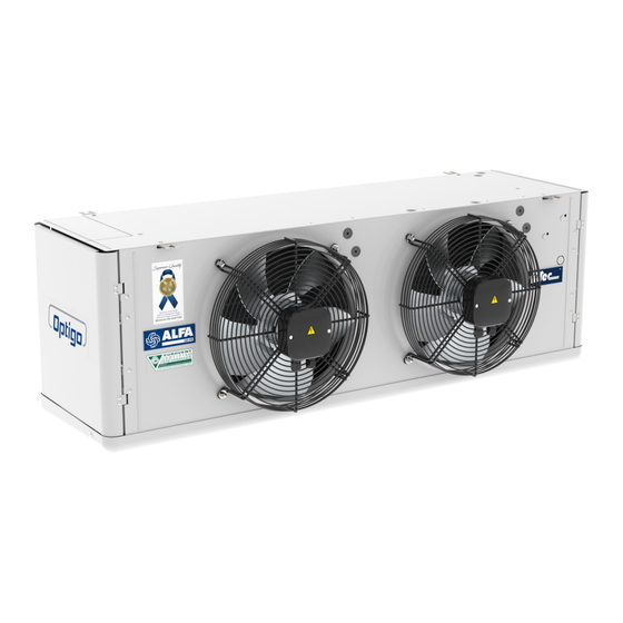
Standard fin spacings: 4.5, 6, 7 mm; 9 mm only for F31MC and F35MC. • Optigo FMC coolers are available with 1 to 4 fans fitted with high efficiency AC & EC fan motors drawing through the coil Motors with external rotor for Optigo F31MC and F35MC models. -
Page 8: Options
Code description F27MC E A * AL BP - * FRH Optigo FMC cubic commercial unit coolers (F27MC=Ø 275 mm, F31MC=Ø 315 mm, F35MC=Ø 350 mm) Refrigerant system (E=HFC, X=CO2, W=brine) Fan motor type (A=AC, E=EC) Number of fans (1 to 4) Coil type (1, 2) Fin spacing (4=4.5, 6=6.0, 7=7.0, 9=9.0 mm) -
Page 9: Product Labels
Product labels ④ ③ ① ② 1. Product label This label is positioned inside the casing. Manufactured by SEST-LUVE-POLSKA sp. z. o. o. Model Refer to paragraph "2.4 ul. Wyczólkowskiego 30, Code description" 44-109 Gliwice, Poland HEAT EXCHANGER Product code Communicate these when Product Serial nr. -
Page 10: Transport And Storage
2. Precharge warning Only for FMCE and FMCX units. Units are delivered from the manufacturer with an overpressure. Check pressure on the Schrader valve. With unpressurised unit: immediate report to manufacturer and note on bill of delivery. 3. Electrical warning Electrically powered component. -
Page 11: Unpacking And Lifting
Unpacking and lifting FMC models are delivered on a wooden pallet, either covered with a reinforced cardboard box or a wooden crate (F35MC models with 4 fans). Handling and positioning can take place manually (smaller models) or with use of a forklift. Packed air coolers may be stacked during trans- max. -
Page 12: Units Packed With Crate
Units packed with crate Place the unit on the ground and loosen the fix- ing materials from the top crate. Remove top crate. Unpacked coolers must be turned before mount- ing. Manually turn the air cooler into mounting posi- tion on a second wooden pallet. Use adequate protective material to prevent the driptray from damaging. -
Page 13: Installation
Installation Mounting dimensions 3/4'' GAS Dimensions (mm) Model n. of fans F27MC F27MC 1050 F27MC 1420 1152 F27MC 1790 1522 F31MC F31MC 1220 F31MC 1670 1392 F31MC 2120 1842 F35MC F35MC 1425 1152 F35MC 1980 1707 F35MC 2535 2262 1131 Coolers must be hung such that the coolers can contract and expand somewhat. -
Page 14: Mounting Bracket
Mounting bracket Use suitable studs when mounting the unit to the ceiling. Fix the unit to cold room ceiling by securely Ø 10 mm tightening nuts and washers. Technical spaces Heat exchangers should be positioned such that the following criteria are met: •... -
Page 15: Refrigerant Connections
Refrigerant connections All pipework and connections must be made in accordance with good refrigeration design and installation practice. Ensure that no stresses are transmitted to the pipework. All pipework should be adequately attached to the walls/ceilings of the cold room and not only to the cooler itself. Pipework must be adequately supported to prevent vibration or external load on the cooler headers, etc. -
Page 16: Pressure Test
Pressure test Ts'=cold room air inlet temperature. Te=evaporating temperature. It is related to the refrigerant pressure on the unit cooler outlet. Trs=refrigerant superheat temperature, on suc- tion line near thermostatic valve bulb. (Trs-Te)=superheat (Trs-Te) ≤ 0.7 x (Ts'-Te) Keep the superheat as low as possible to obtain maximum unit cooler performance. -
Page 17: Electrical Connections
Electrical connections All electrical connections must be made in accordance with the locally valid regulations and in con- formance with good installation practice. The site supply voltage, frequency, accepted power rating and number of phases must comply with the details on the technical documentation. All electrical supply lines must be connected to the terminal boxes through suitable waterproof glands using bot- tom entry or, in case of horizontal installation, the cable is routed to form a water trap. -
Page 18: Fan Motors Connections
Fan motors connections The maximum load of the motors and the recommended settings for the overload relays are to be respected. The built-in thermal overload protection must be integrated in the control circuit when a connection in the terminal box is present. The electrical control circuit should be arranged with a manual reset device in order to prevent continuous on/off switching (tripping) of the motors. - Page 19 For F31MC and F35MC with EC motors: Junction box - 2 speed fans brown grey yellow/green black high speed LINE 230/1 L-N-SL low speed LINE 230/1 31369765EN-07 Alfa LU-VE is a trademark registered and owned by LU-VE Group. Alfa LU-VE reserves the right to change specifications without prior notification.
-
Page 20: Switch (Optional)
6.10 Switch (optional) Each unit can be equipped with a single external switch. Connect the external switch to the central connection box, as shown in the picture. Fans cable J.B. Line cable 3G0.75 6.11 Defrost Always refer to the electrical scheme for both connections and nominal voltage of the electrical defrost option. -
Page 21: Defrost Connections (F27Mc Models - Optional)
6.12 Defrost connections (F27MC models - optional) Ensure complete electrical isolation before performing any wiring. F27MC Electric defrost in coil (E) n. of fans W (x1) W tot 1220 1080 2160 1540 3080 2000 4000 Fan shroud heater (FRH) n. of fans W (x1) W tot In case both E and FRH are mounted, the total power consumption is the sum of each consump-... - Page 22 Heavy electric defrost Electric defrost in coil (E) n. of fans W (x1) W tot 1830 1080 3240 1540 4620 2000 6000 Driptray heater (HD) n. of fans W (x1) In case both E and HD are mounted, the total power consumption is the sum of each consumption. F27MC 31369765EN-07 Alfa LU-VE is a trademark registered and owned by LU-VE Group.
-
Page 23: Defrost Connections (F31Mc Models - Optional)
6.13 Defrost connections (F31MC models - optional) Ensure complete electrical isolation before performing any wiring. F31MC Electric defrost in coil (E) Driptray heater (HD) n. of fans coil type W (x1) W tot W tot 1700 2550 1450 2900 1450 4350 2025 4050... - Page 24 F31MC Terminal x1 = max 40 A 1~230 V 50-60 Hz F31MC 1~230 V 50-60 Hz Terminal x1 = max 40 A 3~400 V 50-60 Hz 3~230 V 50-60 Hz standard 31369765EN-07 Alfa LU-VE is a trademark registered and owned by LU-VE Group. Alfa LU-VE reserves the right to change specifications without prior notification.
-
Page 25: Defrost Connections (F35Mc Models - Optional)
6.14 Defrost connections (F35MC models - optional) Ensure complete electrical isolation before performing any wiring. F35MC Electric defrost in coil (E) Driptray heater (HD) n. of fans coil type W (x1) W (x1) W tot 2075 2975 3680 5280 1150 7620 7620 1150... - Page 26 F35MC Terminal x1 = max 40 A 1~230 V 50-60 Hz 3~400 V 50-60 Hz 3~230 V 50-60 Hz standard 31369765EN-07 Alfa LU-VE is a trademark registered and owned by LU-VE Group. Alfa LU-VE reserves the right to change specifications without prior notification.
- Page 27 F35MC Terminal x1 = max 40 A 1~230 V 50-60 Hz 3~400 V 50-60 Hz 3~230 V 50-60 Hz standard 31369765EN-07 Alfa LU-VE is a trademark registered and owned by LU-VE Group. Alfa LU-VE reserves the right to change specifications without prior notification.
-
Page 28: 6.15 Insulated Suction Hood Mounting
6.15 Insulated suction hood mounting By default, insulated suction hood is supplied loose and shall be assembled before mounting the unit to the ceiling. Support brackets are premounted on the suction hood sides (one per side). Remove the bracket central screw. Loosen the upper and lower screws and slip off the brackets. - Page 29 Hook the central clip to the air cooler casing. Mount the unit equipped with the suction hood to the ceiling. Fix the suction hood to the room ceil- ing by using suitable studs and securely tighten- ing nuts and washers. In 3-4 modules units, there are 3 fixing points.
-
Page 30: Shut-Up Sock Installation (F31Mc And F35Mc Models - Optional)
6.16 Shut-up sock installation (F31MC and F35MC models - optional) The kit is supplied loose and it consists of the shut-up sock and a fan ring adapter. The shut-up sock can’t be used if the adapter is not installed. The fan ring adapter installation procedure depends on the motor type and whether the fan shroud heater (FRH) option is present. - Page 31 Fan ring adapter installation - F31MC with AC fan motor + FRH Temporarily remove the fan guard fixings. Unscrew only the 3 points as indicated in the picture to prevent the guard falling accidentally. In order to avoid crushing of the FRH wires align the sock ring slot with FRH spring.
- Page 32 Fan ring adapter installation - F31MC with EC fan motor Temporarily remove the fan guard fixings. Unscrew only the 3 points as indicated in the picture to prevent the guard falling accidentally. Fix the sock ring on the fan guard by using the washer and the blind nut previously removed.
- Page 33 Fan ring adapter installation - F31MC with EC fan motor + FRH Temporarily remove the fan guard fixings. Unscrew only the 3 points as indicated in the picture to prevent the guard falling accidentally. In order to avoid crushing of the FRH wires align the sock ring slot with FRH spring.
- Page 34 Fan ring adapter installation - F35MC with AC/EC fan motor Temporarily remove the fan guard fixings. Unscrew only the 3 points as indicated in the picture to prevent the guard falling accidentally. Fix the sock ring on the fan guard by using the 2 washers and the blind nut previously removed.
- Page 35 Fan ring adapter installation - F35MC with AC/EC fan motor + FRH Temporarily remove the fan guard fixings. Unscrew only the 3 points as indicated in the picture to prevent the guard falling accidentally. In order to avoid crushing of the FRH wires align the sock ring slot with FRH spring.
- Page 36 Shut-up sock mounting Once the fan ring adapter is installed, place the shut-up sock such that the belt is mechanically blocked by the rounding on the fan ring adapter. Slacken the shut-up sock belt. Let the sock over- lap the sock ring. Fasten the belt. Fasten again the belt, tighter.
-
Page 37: Maintenance
Maintenance It is essential after delivery that adequate protection and inspection are carried out on the equip- ment. This is especially important if there is any delay in installing or commissioning the equipment. After commissioning and setting up the defrost systems, the heat exchanger will require mainte- nance. -
Page 38: Electric Defrost Elements Replacement
Electric defrost elements replacement Before handling heater elements always: • disconnect power supply • ensure heaters are at ambient temperature. To remove electric defrost elements (E), open the driptray and side covers on both sides. Disconnect heater element from connection box. F27MC F31MC F35MC... -
Page 39: Driptray Heater Elements Replacement
Restore electrical connections and close side covers and driptray. 9 (U) Driptray heater elements replacement Before handling heater elements always: • disconnect power supply • ensure heaters are at ambient temperature. F27MC F31MC F35MC To remove driptray heater elements (HD), open the driptray. -
Page 40: Fan Replacement (F27Mc Models)
Fan replacement (F27MC models) Unscrew the fixing screws and remove the fan grid. Unscrew fixing bolts and remove old fan. Remove elctrical connections. Mount new fan in identical position. Use an anti- corrosion compound when remounting the fixing bolts. Restore electrical connections. Remount the fan grid. -
Page 41: Fan Shroud Heater (Optional)
7.11 Fan shroud heater (optional) Unscrew the fixing screws and remove the fan grid. F27MC F31MC F35MC • Position the fan shroud heater around the fan cowl. • Place the three brackets as shown and fix them with the self-tapping screws. •... -
Page 42: Thermostatic Expansion Valve (Optional)
7.12 Thermostatic expansion valve (optional) Units fitted with thermostatic expansion valve have a pre-assembled orifice according to the specifi- cations supplied at units delivery. Remove the adapter and braze the inlet line. Check that the orifice complies with the specifications. Remount the orifice and the adapter respecting the torque wrench setting. -
Page 43: Residual Risks
Residual risks Sharp edges & corners • There is a substantial risk of injuries due to sharp edges and corners of coil and casing. Make sure to wear reliable protection during any handling of the unit and maintenance activities. • Drip tray Ensure the drip tray is empty before lowering or disassembling. -
Page 44: Troubleshooting
Troubleshooting Fault Possible cause Required action Fan motor not functioning No power supply Check/restore power supply. No control signal (EC motors) Check/restore control signal. Fan blade blocked Remove obstruction. Fan motor burnt - Check for fan blade obstructions. - Check thermal protection device. - Replace fan motor. -
Page 45: Spare Parts
10 Spare parts Contact your local Alfa LU-VE representative for spare parts order and assistance. 10.1 Spare parts (F27MC models) ⑤ ④ ③ ① ② ⑥ ⑦ Spare parts Optigo F27MC Electric defrost (E) Fan motor Impeller Fan grid Fan shroud heater (FRH) Driptray heater (HD) Driptray 31369765EN-07... -
Page 46: Spare Parts (F31Mc And F35Mc Models)
10.2 Spare parts (F31MC and F35MC models) ③ ② ① ④ ⑤ Spare parts Optigo F31MC and F35MC Electric defrost (E) Fan motor Fan shroud heater (FRH) Driptray heater (HD) Driptray 31369765EN-07 Alfa LU-VE is a trademark registered and owned by LU-VE Group. Alfa LU-VE reserves the right to change specifications without prior notification. - Page 48 alfa.luvegroup.com...
Need help?
Do you have a question about the Optigo FMC and is the answer not in the manual?
Questions and answers