Table of Contents
Advertisement
Quick Links
Advertisement
Table of Contents

Related Manuals for amc VIBRO AVM 1002D


Summary of Contents for amc VIBRO AVM 1002D
- Page 1 AV MONITOR 1002D VIBRATION MONITORING SYSTEM WITH RELAY OUTPUTS USER MANUAL amc VIBRO Sp. z o.o. Pilotow 2e, 2017 31-462 Krakow, Poland T: +48 (12) 362 97 60 S: + 48 (12) 362 97 63 info@amcvibro.pl KRS No.: 0000618618 REGON No.: 364497010 VAT No.: 6772403385...
-
Page 2: Table Of Contents
Module dimensions ................................5 Mounting ....................................5 Electrical connectors ................................6 Activation ....................................6 Configuration of AVM 1002D ............................7 Entering the menu..............................7 Setting up of the alarm threshold ‘A’ ........................ 7 Setting up of the warning threshold ‘U’ ......................8 Setting up of the threshold activation delay ‘d’... -
Page 3: Introduction
In addition, the relay outputs can be used as safety features. If alarm level is exceeded, AVM 1002D module can turn off the unit before critical damage occurs. -
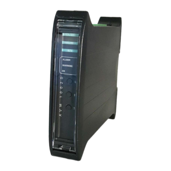
Page 4: Front Panel Description
2. Front panel description Measurement chain diagnostics for IEPE sensor: » LEDs: open - open circuit or sensor failure short - short circuit or sensor failure Indicator of the selected estimate: » Green LEDs: RMS – RMS value of vibration signal ... -
Page 5: Module Dimensions
3. Module dimensions 4. Mounting AVM 1002D module is designed for mounting on 35mm DIN rain in an upright position. Figure 4-1 // Example of 3 AVM 1002D modules mounted on DIN rail AV MONITOR 1002D... -
Page 6: Electrical Connectors
Figure 5-2 // 4..20mA current loop connection 6. Activation After connecting the power, the AVM 1002D module enters into testing procedure. Subsequently all display’s segments and LEDs will flash for a short period of time. If everything is operating properly, then green OK LED is pulsing with a frequency of approximately 1 Hz. -
Page 7: Configuration Of Avm 1002D
AU – selection of vibration signal estimate. Setting up of the alarm threshold ‘A’ The AVM 1002D has the ability to activate the built-in relay, when the signal from the vibration sensor exceeds the threshold value. To set the alarm threshold one should perform the following procedure: 1. -
Page 8: Setting Up Of The Warning Threshold 'U
‘FF’ value on the display and confirm by pressing the SET button. Setting up of the threshold activation delay ‘d’ In the AVM 1002D module the user can define how long the alarm threshold or the warning threshold should be exceeded before activating the relay output. -
Page 9: Signaling Of The Sensor Failure 'Ca', 'Cu
5. To confirm the change, press the SET button. Signaling of the sensor failure ‘CA’, ‘CU’ For full control of the measurement chain AVM 1002D can activate alarm/warning outputs when the measurement chain or vibration sensor is damaged. Sensor failure alarm can be attributed to the triggering alarm or warning relay. Triggering of the relay occurs after 5 seconds of open/short sensor failure. -
Page 10: Setting Up The Correction Of Values Indicated By The Module 'Sc
Setting up the correction of values indicated by the module ‘SC’ The AVM 1002D module is designed to work with ICP® (IEPE) accelerometers with sensitivity of 100 mV/g, however it is possible to set up set correction of values indicated by the module to adjust the module to a sensor with sensitivity slightly different than 100 mV/g. -
Page 11: Selecting The Measured Vibration Signal Estimate 'Au
Selecting the measured vibration signal estimate 'AU‘ The AVM 1002D module enables measuring RMS or 0-PEAK values of vibration acceleration or velocity. ATTENTION! The configuration must be confirmed using SW1 and SW2 configuration switches described in the following chapter. To select desired estimate one should perform the following procedure: 1. - Page 12 Picture 8-1 // Functions of configuration switches Example: Monitoring of the RMS of the vibration signal velocity, using 3 Hz high pass filter and 10 KHz low pass filter, for 100 mm/s range and internal power loop. The following configuration of the switches must be set: WARNING! The set-up of the switches configuration should be done on a switched off device.
-
Page 13: Menu
9. Menu Graphical representation of menu structure is presented on the following figure. AV MONITOR 1002D... -
Page 14: Technical Parameters
10. Technical parameters PARAMETER VALUE sensor type IEPE, 100mV/g , 8mA/20V measured values velocity, acceleration types of estimates RMS, 0-PEAK power supply 24 VDC (18..36 VDC) power consumption <4 W low-pass filter 1 and 10 kHz, 24 dB/oct., 4 order high-pass filter 3 and 10 Hz, 12 dB/oct., 2 order...
Need help?
Do you have a question about the AVM 1002D and is the answer not in the manual?
Questions and answers