
Subscribe to Our Youtube Channel
Related Manuals for Zamp Solar Pulse Tech CINDER 40 PWM


Summary of Contents for Zamp Solar Pulse Tech CINDER 40 PWM
- Page 1 CINDER™40 PWM Charge Controller CINDER 40 PWM Part # SCC1005 Input: DC12V or DC24V solar panel (Max 50Voc) Output: DC 12V 40A DC 24V 40A User Manual...
-
Page 2: Table Of Contents
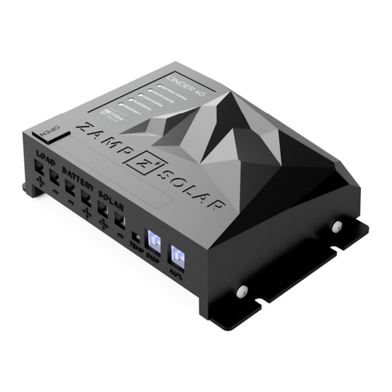
Important Installation Notes - Please Read Device Connections Installation Guide 12-Volt and 24-Volt 12-Volt Installation Specifics 24-Volt Installation Specifics Load Output Circuit Details 5) Zamp Solar Mobile Application Status Page History Page Settings Page 6) PulseTech Functionality 7) Charging Profiles... - Page 3 CINDER 40 PWM Charge Controller User Manual Zamp Solar Figure 1: CINDER 40 Top View Figure 2: Front face of CINDER 40 showing all connections...
-
Page 4: Important Safety Instructions - Please Read
● Be very careful not to connect the wires to the solar panel or battery in reverse. (See Figure 2 above for connection layout) ● Do not disassemble the CINDER 40. Please contact Zamp Solar Customer Service if you have any problems with your device. 541-728-0924 or support@zampsolar.com. -
Page 5: Overview
2) Overview Intro The Zamp Solar CINDER 40 solar charge controller automatically controls the attached solar input to charge the connected battery and keep it at optimal battery health. The CINDER 40 also monitors, regulates and protects the attached solar and battery components. -
Page 6: Features
Available for both Android and iOS. (see Section 5 for more details on the Zamp Solar Application) 6. Robust safety and protection a. Protects battery from over-voltage or over-current scenarios b. -
Page 7: Wiring And Installation
7. Immediately after connecting the battery to the charge controller, use the Zamp Solar Mobile App to set the proper battery charging profile or use the custom profile settings to adjust the charging profile. Do this before connecting your solar panels to the device. -
Page 8: Device Connections
Battery connection terminals. (-) goes to the negative side of the battery. (+) goes to the positive side of the battery. Zamp Solar strongly recommends installing a 50-amp fuse inline on the positive wire leading to the battery. Connect the battery wiring first, then the solar panel wiring. -
Page 9: Installation Guide 12-Volt And 24-Volt
CINDER 40 PWM Charge Controller User Manual Zamp Solar Installation Guide 12-Volt and 24-Volt Charge Controller to Battery Wiring Connect the charge controller to the battery using 10 feet (or less) of 6-AWG, 90 C copper wire. The shorter the wire run, the better. This is due to the voltage drop that occurs in the wires when the device is charging. -
Page 10: 12-Volt Installation Specifics
CINDER 40 PWM Charge Controller User Manual Zamp Solar 12-Volt Installation Specifics Table 1: 12-Volt Installation Quick information Maximum Nominal Panel Wattage 800W (<= 40A Isc) Battery to Charge Controller Wire Size 6-AWG Battery to Charge Controller Fuse Size Battery to Charge Controller Maximum Wire Length with 6-AWG... - Page 11 Zamp Solar Figure 6: 12-Volt Charge Controller to Solar Panel Wiring example Figure 6 demonstrates how to connect two panels in parallel using a Zamp solar parallel connecting roof cap to create a 12-volt charging system. This configuration should be used when your battery is 12-volts.
-
Page 12: 24-Volt Installation Specifics
CINDER 40 PWM Charge Controller User Manual Zamp Solar 24-Volt Installation Specifics Table 2: 24-Volt Installation Quick information Maximum Nominal Panel Wattage 1600W (<= 40A Isc) Battery to Charge Controller Wire Size 6-AWG Battery to Charge Controller Fuse Size Battery to Charge Controller Maximum Wire Length with 6-AWG... - Page 13 CINDER 40 PWM Charge Controller User Manual Zamp Solar Figure 8: 24-Volt Charge Controller to Solar Panel Wiring example Figure 8 demonstrates how to connect 4 panels in a 2x2 series configuration using Zamp solar series connecting roof caps to create a 24-volt charging system. This configuration should be used when your battery is 24-volts.
-
Page 14: Load Output Circuit Details
The load terminals give a user-controlled, 20-amp, fuse protected output circuit that discharges from the battery. The Zamp Solar app allows you to turn your load on/off as well as monitor the load output at all times so you can see how much power is being used by your attached electronics. -
Page 15: Zamp Solar Mobile Application
Zamp Solar 5) Zamp Solar Mobile Application Find the Zamp Solar App on the Google Play Store or on the iOS App Store by searching “Zamp Solar”. The CINDER 40 PWM controller can be controlled using the Zamp Solar application available on both Android and iOS devices. -
Page 16: Status Page
CINDER 40 PWM Charge Controller User Manual Zamp Solar Status Page Real Time Data ● Graph Select Buttons: These two buttons are labeled “Real Time Solar” and “Real Time Load”. The option that is highlighted in green will be displayed below on the graph. - Page 17 CINDER 40 PWM Charge Controller User Manual Zamp Solar Status Indicator Light Descriptions Table 4: Status LED Descriptions Indicator LED Status Bulk/Soft (CC) Absorption/Float (CV) Idle/Start Solar Input (Charging <=40A <0.3 A Current) Green Solar Input (Charging >40A OR Negative Current >0.3A OR Negative Current...
-
Page 18: History Page
CINDER 40 PWM Charge Controller User Manual Zamp Solar History Page System History ● Historical Data Options: This button allows you to change the History graph to any of the following options: Solar Energy Production ● Max Daily Wattage ●... - Page 19 CINDER 40 PWM Charge Controller User Manual Zamp Solar Battery Profile Details ● Select to view the details of the active Battery Profile. If Float is not active, then it will not appear in the details section. Load Configuration Settings ●...
- Page 20 Zamp Solar Updating Device Firmware If you need to update the Device Firmware (FW) for any reason, follow the instructions below. ● Use the Zamp Solar App to connect to your CINDER 40 ● Navigate to the Settings Page ●...
-
Page 21: Pulsetech Functionality
CINDER 40 PWM Charge Controller User Manual Zamp Solar 6) PulseTech Functionality The CINDER 40 controller contains a proprietary, patented PulseTech pulsing circuit that has been scientifically proven to extend the life of all types of lead acid batteries. This is achieved using PulseTech’s patented pulsing technology that breaks up the lead sulfates that build up... -
Page 22: Charging Profiles
CINDER 40 PWM Charge Controller User Manual Zamp Solar 7) Charging Profiles The CINDER 40 contains six pre-programmed, multi-stage battery profiles that have been customized to each specific battery type. There are profiles for AGM, Gel, Conventional lead-acid (WET), Lithium (Lithium Ion & LiFePo4), LTO (Lithium Titanate Oxide), and Calcium Batteries. - Page 23 CINDER 40 PWM Charge Controller User Manual Zamp Solar Table 6: Allowed Custom Charging Profile Voltage Ranges Custom Charging Profile Voltage Ranges This table shows the 12V system voltage, double the voltage given for a 24V system Battery Type Absorption...
-
Page 24: Led Operation
CINDER 40 PWM Charge Controller User Manual Zamp Solar 8) LED Operation Battery Status LED This LED gives the current charging state of the controller. Solid Green = Float/Fully charged Fast Blinking Green = Absorption Solid Orange= Bulk Charging Slow Blinking Orange (once every 2... -
Page 25: Troubleshooting
CINDER 40 PWM Charge Controller User Manual Zamp Solar 9) Troubleshooting Battery Removal Procedure If you are going to remove your battery during a period of very low Solar Input (i.e. nighttime, inside a shop with no lighting, etc.) you must also remove the solar panel input. If you remove the battery input and leave a weak solar input, the controller will consider its power source too variable and enter a shutdown state. -
Page 26: Specifications
CINDER 40 PWM Charge Controller User Manual Zamp Solar 10) Specifications Table 9: Specifications for CINDER 40 Specification Details Battery Voltage 12/24V (Automatically Detected) Minimum Voltage on Battery Terminals Maximum Voltage on Battery Terminals Rated Charge Current Minimum Solar Input Voltage to Charge... -
Page 27: Contact Us
CINDER 40 PWM Charge Controller User Manual Zamp Solar Figure 3: CINDER 40 Mounting Diagram 11) Contact Us Zamp Solar 62355 NE Jamison Street Bend, OR 97703 support@zampsolar.com www.zampsolar.com Phone: 541-728-0924...
Need help?
Do you have a question about the Pulse Tech CINDER 40 PWM and is the answer not in the manual?
Questions and answers