Table of Contents
Advertisement
Quick Links
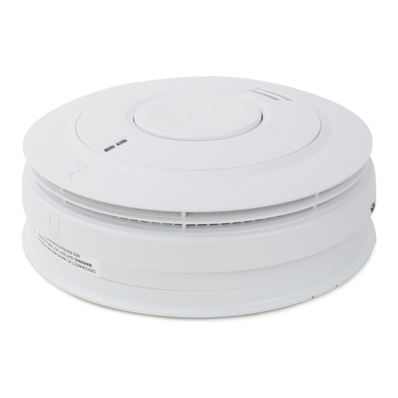
Ei160e Series
230V~ SMOKE & HEAT ALARMS
with Rechargeable Battery Backup
Instruction Manual
Contact Us
Aico Ltd
Mile End Business Park, Maesbury Rd, Oswestry,
Shropshire SY10 8NN, U.K.
Tel: 01691 664100
www.aico.co.uk
Ei Electronics
Shannon, Co Clare, Ireland.
Tel: 061 471277
www.eielectronics.com
P/N B18148 Rev4
© Ei Electronics 2018
1
Advertisement
Table of Contents

Related Manuals for Aico Ei160e Series


Summary of Contents for Aico Ei160e Series
- Page 1 Ei160e Series 230V~ SMOKE & HEAT ALARMS with Rechargeable Battery Backup Instruction Manual Contact Us Aico Ltd Mile End Business Park, Maesbury Rd, Oswestry, Shropshire SY10 8NN, U.K. Tel: 01691 664100 www.aico.co.uk Ei Electronics Shannon, Co Clare, Ireland. Tel: 061 471277 www.eielectronics.com...
-
Page 2: User Section
User Section Introduction to Ei160e Smoke/Heat Alarms The Ei160e series is supplied with an Easi-Fit base that allows very quick and simple installation of the Smoke Alarm, combined with simple detector head removal and replacement. The Easi-Fit base automatically connects both mains power and battery as the detector head slides on to the Easi-Fit base. - Page 3 Testing and Maintenance Check all Alarms monthly, especially after initial installation or re-occupation (e.g. following a holiday). 1. Check that the green mains indicator light is on. (if it is off check circuit breakers, fuses and wiring etc.) 2. Check that the red LED on the cover flashes once every 40 seconds to indicate normal operation –...
- Page 4 The modules Ei100MRF (if required) must be re-fitted to the Alarms and the Alarms must be re-attached to the mounting plates when the premises are re-occupied. (Long term storage (over 1 year) can damage the batteries such that they will not recharge when the units are re-connected to the mains supply).
-
Page 5: Silence Feature
Nuisance / False Alarms When sure that it is just a nuisance/false alarm, simply press the “> <” button briefly on the Alarm to silence the unit for 10 minutes. If, when the alarm goes off, there is no sign of smoke, heat or noise to indicate that there is a fire, you should get your family into a safe place, before you start investigating. - Page 6 Planning Your Escape Route Use the Smoke / Heat Alarm Test buttons “> <” to familiarise your family with the Alarm sound and to practice fire drills regularly with all family members. Draw up a floor plan that will show each member at least 2 escape routes from each room in the house.
- Page 7 / Heat Alarm as recommended in the ‘INSTALLER INSTRUCTIONS’ section significantly improves the probability of early detection. • The Alarm may not be heard. • A Smoke / Heat Alarm may not wake a person who has taken drugs or alcohol. •...
- Page 8 (4) If alarm does not stop, switch off mains and remove unit - see “Important Information” section. (Only remove the alarm with the red light flashing, the others are probably satisfactory). 2. LOW BATTERY & OTHER BEEPS: Check the green mains power light is on. If not, check fuse, circuit breakers and wiring connections.
-
Page 9: Fire Safety
The crossed out wheelie bin symbol that is on your product indicates that this product should not be disposed of via the normal household waste stream. Proper disposal will prevent possible harm to the environment or to human health. When disposing of this product please separate it from other waste streams to ensure that it can be recycled in an environmentally sound manner. -
Page 11: Installer Section
Installer Section Installation Guide LOCATE CORRECT SITING POINT ALARM SHOULD BE CEILING MOUNTED AT LEAST 300mm FROM WALLS & OBSTRUCTIONS, IDEALLY CENTRALLY IN ROOM/AREA FIX & WIRE BASEPLATE WIRE TO TERMINALS ON THE BASEPLATE AND FIX BASEPLATE TO CEILING USING THE FIXINGS PROVIDED SLIDE ON ALARM SLIDE ALARM ONTO BASEPLATE. - Page 12 How Many Alarms To Install - Categories & Grades The advice here follows the guidance in British Standard BS 5839-6: 2013 in general (for further information see the BS standard itself). The main reason for fitting Smoke & Heat Alarms in dwellings is to ensure that when there is a fire, sufficient early warning is given so that everybody can escape safely.
- Page 13 UK Requirements (BS 5839-6:2013) OPTIMUM PROTECTION for dwellings where occupants may be at high risk (e.g. elderly) Optimum Protection LD1: As LD2, but in addition Smoke or Heat Alarms should be located in all rooms and other areas of the dwelling. (apart from toilets or bathroom) Interconnect all Alarms BASIC PROTECTION...
- Page 14 ROI Requirements (IS 3218:2013) OPTIMUM PROTECTION for dwellings where occupants may be at high risk (e.g. elderly) Optimum Protection LD1: As LD2, but also including attics / lofts / other spaces in which a fire might start (apart from toilets or bathroom). Interconnect all Alarms BASIC PROTECTION for new or materially altered dwellings or existing dwellings...
-
Page 15: Selecting Alarm Type
Selecting Alarm Type Optical/Ionisation/Heat Alarm Selection Locations & Performance Alarm Type Optical Ionisation Heat Locations Hall, Corridors, Escape Routes Kitchens Living Rooms Bedrooms Shower / Bathroom Fire Response Slow Smouldering Fires (polyurethane foam, ignited bedding etc.) Fast Flaming Fires (chip pans, flaming wood/plastic, oil, solvents etc.) Temperature >58 (only in areas with cooking fumes, steam,... -
Page 16: Locations To Avoid
Positioning Alarms he locations must comply with applicable building regulations. Hot smoke rises and spreads out, so a central ceiling position is the preferred location. The air is “dead” and does not move in corners, therefore Smoke & Heat Alarms must be mounted away from corners. - Page 17 • Near a decorative object, door, light fitting, window moulding etc., that may prevent smoke or heat from entering the Alarm. • Surfaces that are normally warmer or colder than the rest of the room (e.g. attic hatches). Temperature differences might stop smoke or heat from reaching the unit.
-
Page 18: Mounting & Wiring Alarms
WARNING: Mains operated Alarms should be installed and interconnected by a qualified electrician in accordance with the Regulations for Electrical Installations published by the Institution of Electrical Engineers (BS7671). Failure to install this Alarm correctly may expose the user to shock or fire hazards. WARNING: The Alarm must be continuously powered 24 hours a day so it is important that it is not on a circuit that can be turned off by a switch. - Page 19 • check that the Interconnect wire is NOT connected to Live, Neutral or Earth. Do not use an Earth wire for the Interconnect line. N.B. The Alarm does not need to be earthed. However the terminal marked is provided for the convenience of the installer so that any copper Earth wire or cable coloured green &...
-
Page 20: Interconnecting Alarms
Ensure the alarm operates correctly - see “TESTING & MAINTENANCE” section on page 3. Interconnecting Alarms Note: A maximum of twelve Ei161e / Ei164e / Ei166e Smoke or Heat Alarms may be interconnected. Up to 8 additional accessories may also be connected. If you wish to connect more than 12 Alarms contact your local distributor.
Need help?
Do you have a question about the Ei160e Series and is the answer not in the manual?
Questions and answers