
Related Manuals for Sedgwick PT255


Summary of Contents for Sedgwick PT255
- Page 1 PT255 PLANER THICKNESSER OPERATION AND MAINTENANCE INSTRUCTIONS MACHINE SERIAL NO. Designed & Manufactured in the U.K. KEEP SAFE FOR FUTURE USE...
- Page 2 DECLARATION OF CONFORMITY ORIGINAL Business Name and Full Address of Manufacturer M. Sedgwick & Co. Ltd. - Stanningley Field Close, Leeds LS13 4QG Description of product (Commercial Name) Model PT255 Planer Thicknesser Function, Model, Type Function: Woodworking Machine Model: PT255...
-
Page 3: Table Of Contents
List of Contents Introduction: Design, Purpose and Technical Specification 1.0 Safety 1.1 Personal Protective Equipment 1.2 Residual risks 2.0 Machine Handling 2.1 Positioning 2.2 Storage 2.3 Disposal 3.0 Connection to a Dust Extraction System 3.1 Chip Extraction Hood 4.0 Electrical Installation 5.0 Switchgear 5.1 The Padlockable Isolator 5.2 Start/Stop Buttons... - Page 4 Introduction This instruction manual is designed for you in accordance with current UK regulations and EU law, in particular the European Machinery Directive 206/42/EC. It describes how to operate the machine properly and safely. This manual is an integral part of the machine and must therefore be kept accessible at all times.
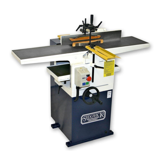
- Page 5 Illustration FENCE TILT LOCK FENCE LATERAL LOCK REAR CUTTERBLOCK GUARD REAR MACHINE GUARD SURFACE TABLE RISE AND FALL HANDLE CUTTERBLOCK GUARD HORIZONTAL LOCK MOTOR SWITCHGEAR CUTTERBLOCK GUARD VERTICAL LOCK THICKNESSING TABLE THICKNESSING TABLE RISE VERTICAL LOCK AND FALL OPTIONAL FOOT OPERATED STOP SWITCH...
- Page 6 Technical Specification SURFACE CAPACITY 255 mm THICKNESSING WIDTH 255 mm THICKNESSING DEPTH 180 mm SURFACE TABLE LENGTH 1200 mm INFEED TABLE LENGTH 600 mm SURFACE TABLE HEIGHT 830 mm THICKNESSING TABLE LENGTH 600 mm CUTTERBLOCK DIAMETER 80 mm CUTTERBLOCK KNIVES CUTTERBLOCK SPEED 4000 rpm FEED ROLLER DIAMETER...
-
Page 7: Safety
Safety To ensure that this machine is operated safely, machinists must be properly trained and must read, understand and observe the requirements of this manual. Hazards may arise if the machine is used by untrained individuals or if it is used for purposes other than for those for which it was designed. -
Page 8: Machine Handling
• Risk of injury through accidental contact with the rotating cutterblock – do not attempt to remove any guarding from the machine during machining; • Risk of injury due to ejected workpieces; • Risk of injury from workpiece kickback when surface planing; •... -
Page 9: Positioning
Never lift the machine by its planer tables. To do so would seriously damage their alignment. Upon arrival, check that the machine has not suffered any damage during transit. Reuse or recycle any packaging materials, e.g. wooden pallet, and where not possible to do so, dispose of them in accordance with local refuse requirements. - Page 10 435mm 345 mm You must ensure that there is an ample power supply available to operate the machine, together with good lighting and ventilation. Do not operate or store the machine outdoors. Ensure the environment for operating woodworking machinery is kept clean and tidy and damp- free.
-
Page 11: Storage
2.2 Storage Keep the machine sealed in its original packaging until required for assembly/installation and be sure to observe the machine handling advice on the outside of the packaging. Store under the following conditions: • Store indoors in a dry and dust-free environment; •... -
Page 12: Electrical Installation
For Surfacing The hood is designed to sit on the thicknessing bed, and should be inserted hollow side up, with the exhaust outlet below the fixed outfeed table. The lug on the underside of the hood, attached to the exhaust outlet, should locate against the end of the thicknessing bed, with care being taken that the anti-kickback fingers are not... - Page 13 Should you encounter problems on start-up check for the following likely causes: PROBLEM LIKELY CAUSE CORRECTIVE ACTION Fails to start Main supply switched off Check main switch Overload tripped Reset overload Fuse blown Check and replace fuses (check all three on three phase) Loose wire Check all connections...
-
Page 14: Switchgear
5.0 Switch Gear 5.1 The Padlockable Isolator When this switch is in the OFF position, the machine is effectively isolated from the electrical supply to allow personnel safe access for maintenance or repair work and to prevent dangerous restarts. In order to prevent unauthorised use of the machine the switch can also be secured in the OFF position using a padlock. -
Page 15: Guarding
6.0 Guarding All guards should be checked at the beginning of each working shift for damage etc. 6.1 The Front Cutterblock Guard The yellow pillar mounted guard at the front of the machine is known as the bridge guard. The bridge guard covers the cutterblock when surface planing. -
Page 16: The Cutterblock
7.0 The Cutterblock The concept of the TERSA cutterblock is to allow the automatic clamping of the cutters using centrifugal force. The exactness of the position is +/- 0.02mm, guaranteed on all the sharp edges and on the whole length of the planing shaft. For correct use of the tool it is recommended that a suitable product is used to occasionally clean the support runner of the cutters. -
Page 17: Preparations For Machining
SLIDE THE BLUNT KNIFE FROM OUT OF THE SIDE OF THE CUTTERBLOCK AND EITHER REINSERT IT WITH AN UNUSED SIDE UP OR REPLACE IT WITH A NEW ONE. THE CUTTERS WILL AUTOMATICALLY CLAMP ON START UP. IN ORDER TO ENSURE THAT THEY ARE CORRECTLY SEATED THICKNESS A 300 OR 410mm WIDE PIECE OF TIMBER INTENSIVELY ACROSS THE FULL CUTTING... -
Page 18: Surface Planing
9.0 Surface Planing Caution: Ensure that all stock is clear of the blades before start-up. When surfacing, the depth of cut is set by adjusting the height of the infeed table, using the Surface Table Rise and Fall Handle. The outfeed table is already set level with the cutting circle of the cutterblock. - Page 19 Workpieces longer than the in and out-feed surfacing tables should be supported, e.g. by extension tables or roller supports. Unless very thick material is being planed, flatting should be the safest of operations on a hand fed planer, provided that all necessary precautions are taken.
-
Page 20: Planing Wide Boards
When flatting a workpiece of more than 75mm thickness the bridge guard must be lowered on to the table and adjusted horizontally to the workpiece. The workpiece should be straightened, with flat hands beside the guard, along the fence. Foot positioning It is important that a good firm and balanced base is made and maintained by the... -
Page 21: Edge Planing (Squaring)
The bridge guard must always be in position when planing bowed boards, as shown: DO NOT operate the surface planer without the bridge guard. The long accepted way of placing the front portion of timber on the outfeed table and taking several cuts off the other end then reversing the timber should not be used. -
Page 22: Bevelling Or Chamfering
During operation the workpiece is pressed up against the fence and the outfeed table by the left hand, fingers closed (thumb on workpiece). This will produce an edge that is square to the face of the timber. The workpiece is moved forward regularly by the right hand, again with the fingers closed and thumbs on workpiece. -
Page 23: Push Blocks And Push Sticks
9.7 Push Blocks and Push Sticks When planing smaller workpieces always use a push stick or push block. In some operations push blocks should be used, especially when planing short or narrow pieces of timber where it is necessary to pass the workpiece between the edge of the bridge guard and fence. - Page 24 Feed rollers at the front and rear of the cutterblock push and pull the wood through the rotating cutter knives. The infeed roller is located at the front of the block and is made of serrated steel. In order for it to operate effectively it must be kept free of resin. Clean off any build up of resin using a stiff brush with a proprietary cleaner or solvent.
-
Page 25: Diagnosing Faults In Planing
11.0 Diagnosing Faults All faults should be reported as soon as they are discovered. Fault Cause Diagnosis The timber rocks, and the cutters Re-set the cutters and check edge is rounded in length alignment with the table. edge straightness, after being surfaced. wear or maladjustment of the slides on the table. -
Page 26: Limitations Of Use And Safe Working Practices
12.0 Limitations of Use and Safe Working Practices The following operations shall not be attempted on planer thicknessing machines, as they cannot be performed safely: stopped work, i.e. any cut which does not involve the full workpiece length, planing of badly bowed timber where there is inadequate contact of the timber on the in- feed table, ... - Page 27 12.1 Noise Noise levels can vary widely from machine to machine depending on conditions of use. Persons exposed to high noise levels, even for a short time, may experience temporary partial hearing loss and continuous exposure to high levels can result in permanent hearing damage. Local laws require employers to take measures to reduce noise levels where any person is likely to be exposed to loud or continuous noise.
-
Page 28: Warning Labels
level of exposure to the work force include the duration of exposure, the characteristics of the workroom, the other sources of dust and noise, etc., i.e. the number of machines and other adjacent processes. Also the permissible exposure levels can vary from country to country. This information, however, will enable the user of the machine to make a better evaluation of the hazard and risk. - Page 29 General caution Check guard Use hearing protection Refer to instruction manual Use protective eyewear Use protective footwear Use protective apron Wear a mask All notices and labels which are affixed to the machine must be kept readable and may not be removed. Any that have become damaged or unreadable must be replaced promptly.
-
Page 30: Machine Data Plates
12.3 Machine Data Plate The data plate is displayed on the back of the machine and provides the following information: M. SEDGWICK & CO. LTD STANNINGLEY FIELD CLOSE LEEDS LS13 4QG UNITED KINGDOM Tel.: 0044 (0) 1132 570637 Fax.: 0044 (0) 1132 393412... -
Page 31: Lubrication
13.1 Lubrication Since your planer thicknesser is constructed of cast iron, which is a porous metal, care should be taken when cleaning. Use mineral spirits and steel wool on all metal parts. Avoid contact with anything moist. Do not set drinks on the table top or leave green wood on it. These will leave permanent marks. - Page 32 back up, replacing firstly the chain, gear train (as per your measurement), and flat belt. Ensure that the chain tensioning sprocket is replaced as follows: Excessive belt wear, vibration and noise may be the cause of poorly aligned or loose pulleys.
-
Page 33: Adjusting The Thicknessing Feed Rollers
13.4 Adjusting the Thicknessing Feed Rollers As the planer knives are sharpened and re-set you may find it necessary to adjust the thicknesser feed rollers to ensure that timber is fed through smoothly. These are set at the right height and pressure at the factory, but may require adjustment to compensate for slight changes to the knife height in the cutterblock. -
Page 34: Planer Tables
13.5 Planer Tables The surface tables are formed from cast iron, and may become warped or bent as a result of neglected maintenance and excessive wear. The dust and vibration from surfacing miles of hard maple or pitch pine, will loosen adjustments and make slideways sticky. A sloppy fit hammers adjoining precision surfaces, and poorly lubricated slideways wear quickly. -
Page 35: Brake Motor Installation & Maintenance
13.7 Brake Motor Installation & Maintenance Installation It is the responsibility of the machine installer to ensure that: The brake functions correctly after final installation; • Earthing has been carried out according to local regulations before connection to the mains; •... - Page 36 14.0 PT255 Planer Thicknesser Parts Diagram...
- Page 37 Planer Thicknesser Parts List PART NO. PART DESCRIPTION 9002 MOTOR MOUNTING 9077 SWIVEL BLOCK 9003 MOTOR PULLEY 9078 TABLE HANDLE 9004 MOTOR ADJUSTING STRAP 9080 FENCE TABLE BRACKET 9005 ADJUSTING STUD 9081 FENCE TABLE BAR 9010 BASE 9082 FENCE SLOTTED BRACKET 9011 RISE AND FALL PILLAR 9083...
- Page 38 3SE0021 PT-1 STARTER 10/12A 3SE0006 PT-3 STARTER 4/6A Use only original spare parts supplied by the manufacturer. The use of unauthorised, counterfeit or inferior parts may result in damage or malfunction.
Need help?
Do you have a question about the PT255 and is the answer not in the manual?
Questions and answers