Advertisement
Quick Links
Advertisement

Related Manuals for Riverbed Steelhead Series


Summary of Contents for Riverbed Steelhead Series
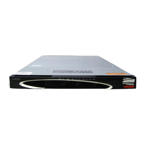
- Page 1 Rack Installation Guide Steelhead Series xx00, xx20, xx50 and Interceptor Systems...
- Page 2 The content of this manual is furnished on a RESTRICTED basis and is subject to change without notice and should not be construed as a commitment by Riverbed Technology, Incorporated. Use, duplication, or disclosure by the U.S. Government is subject to restrictions set forth in Subparagraphs (c) (1) and (2) of the Commercial Computer Software Restricted Rights at 48 CFR 52.227-19, as applicable.
-
Page 3: Table Of Contents
Rack Installation Guide These instructions describe how to install Series 250, 550, 1050, 2050; models 3000, 3010, 5000, 5010; and models 3020, 3520, 5520, 6020, 6120, 9200 in a standard Telco-type rack. It contains the following sections: “Overview,” next “Rack Installation Guidelines” on page 4 “Required Tools and Equipment”... -
Page 4: Rack Installation Guidelines
Overview Depending on your order, some systems require that the inner rails be attached to the chassis before they can be installed to the rack. Square-Hole Post Adaptor Rack cabinets may have square or circular holes in the vertical posts. If necessary, using the included adaptor, you can convert the square post holes to circular holes to accommodate standard screws. -
Page 5: Required Tools And Equipment
The enclosed short rack adaptors (if needed) The enclosed square-hole post converter (if needed) If your system is missing any components please contact Riverbed Technical Support for a replacement part at http://www.riverbed.com. Mounting Series 250 and 550 to a Rack The following section describes how to install a Series 250 or 550 system to a rack. -
Page 6: Mounting Series 1050 And 2050 To A Rack
1. To install the mounting brackets, use the included screw kit to secure the brackets with three screws on each side towards the front of the system. Figure 1-1. Installing Brackets to the System 2. Slide the system into the rack until it is flush against the rack post. The Series 250 and 550 must be installed in a center mount. - Page 7 To open the bezel on Series 1050 and 2050 systems To open the bezel press in the buttons on each side of the bezel and slide towards you. The bezel remains attached to the system on hinges. Figure 2. Opening the Bezel in the 1050 and 2050 Systems Mounting the System to a Four-Post Rack The Series 1050 and 2050 ship with rails pre-installed to the chassis for mounting to a four-post rack.
- Page 8 2. Install the outer rails to the rack posts. Figure 4. Attaching the Outer Rails to the Rack 3. Pulling open the release latch on the inner rails, slide the inner rails into the outer rails, pushing the system into the rack. NOTE: The ball retainer on the outer rail must be returned to the foremost position in order to connect with the inner rail on the chassis.
- Page 9 Mounting the System to a Two-Post Rack The Series 1050 and 2050 can be mounted to a two-post rack in the center-mount position. The following section describes how to remove the pre-installed four-post rails and install the two-post brackets for installation in a two-post rack.
-
Page 10: Mounting Models 3000, 3010, 5000, And 5010 To A Rack
4. Attach the first bracket to the chassis with the three included screws. Figure 8. Attaching Two-post Center-mount Brackets 5. Slide the second bracket onto the pegs of the first bracket by placing the second bracket over the first bracket at the widest opening then sliding towards the narrower part to secure. Figure 9. - Page 11 CAUTION: 3U systems weigh from 62-67 lbs. (28-30 kg). Lift the system using both hands and with your knees bent. 2. To remove the outer rails from the chassis, slide the rail back until the lock button is exposed. Figure 10. Removing the Outer Rails from the Chassis 3.
- Page 12 7. On the front and rear of the rack, insert two screws on the each side of the rack. Do not tighten the screws. Figure 12. Mounting the Rail Hardware onto the Front and Rear of the Rack 8. Place the left and right outer rails onto the front and rear of the rack and tighten the screws. 9.
-
Page 13: Mounting Models 3020, 3520, 5520, 6020, 6120, And 9200 To A Rack
Mounting Models 3020, 3520, 5520, 6020, 6120, and 9200 to a Rack You must install the inner rails to the chassis before you install the outer rails and mount the system to a rack. Before installing the inner rails to the chassis: Unplug the AC power cords. - Page 14 3. Locate the five rail buttons on each side of the chassis and the five corresponding holes on each of the inner rails. (One end of the hole is larger than the other end of the hole.) Figure 16. Locating the Five Chassis Buttons and Rail Holes 4.
- Page 15 Standard Brackets. For rack depths of 28 to 33 inches (71.1 to 83.8 cm) Short Rack Adaptors. For rack depths of 17 to 28 inches (43.2 to 71.1 cm) IMPORTANT: The system produces front-to-back cooling airflow that requires an unobstructed airflow to the fan housing.
- Page 16 To mount the short rack adaptors to the outer rails 1. Slide the standard bracket forward so that the larger end of the hole is aligned with the rail button and pull the bracket off the rail. (One end of the hole is larger than the other end.) Figure 19.
- Page 17 4. Reposition the bracket so that it is the correct depth to fit your rack. 5. Repeat the steps to install the other short rack adaptor. To mount the system on a rack 1. Secure both outer rail assemblies to the rack with the screws and washers. Figure 22.
- Page 18 NOTE: The system may not slide into the rack smoothly or easily when installed the first time. Some adjustment to the slide assemblies might be needed for easy installation. Figure 23. Sliding the System on to the Four-Post Rack NSTALLATION UIDE...
- Page 19 3. Secure the system to the rack by tightening the screws on the front sides of the chassis. Figure 24. Securing the System to the Rack NSTALLATION UIDE...
- Page 20 NSTALLATION UIDE...
Need help?
Do you have a question about the Steelhead Series and is the answer not in the manual?
Questions and answers