
Related Manuals for Automatic Filters Tekleen CSB

Summary of Contents for Automatic Filters Tekleen CSB
- Page 1 AUTOMATIC FILTERS, INC. 2672 S. LA CIENEGA BLVD. LOS ANGELES, CA 90034 310 839 2828 800 336 1942 FAX 310 839 6878 www.tekleen.com info@tekleen.com...
-
Page 2: Table Of Contents
Introduction Description & Operation Technical Data Installation Filter Assembly 9-11 Periodic Checks Filter Parts 13-14 Filter Controls 15-20 ALL RIGHTS RESERVED, THIS MANUAL AND THE INFORMATION CONTAINED ARE NOT ALLOWED TO BE USED WITHOUT WRITTEN PERMISSION FROM AUTOMATIC FILTERS INC. -
Page 3: Introduction
Automatic filters Inc. for industrial, municipal water, sewage systems, and all types of irrigation applications. All products manufactured by Automatic Filters Inc. are easy to install, use and service and don’t require special skills to operate them We would like to wish you many years of satisfied service. -
Page 4: Description & Operation
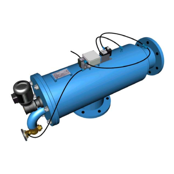
&6% 0$18$/ Description & Operation Filter Assembly General Description (Figure 1) The CSB electric self-cleaning brush filter enables high quality filtration at filtering degrees of 200-4000 micron from different types of fluid sources such as sewage, reservoirs, rivers, lakes, and wells. The CSB filter contains the following parts: 1. - Page 5 &6% 0$18$/ Filter Operation General Description (Figure 2) Filtration Water enters the filter through the “Inlet” (1) and passes through the screen (2), which purifies the water by separating dirt smaller particles from the water. As more water flows through, dirt builds up on the screen. As dirt builds up on the screen is causing to a differential pressure between the in let and outlet Cleaning Process When the difference in pressure ( P) reaches the preset value on the differential...
-
Page 6: Technical Data
&6% 0$18$/ Technical Data Standard Features 3 bar (45 psi) • Minimum operating pressure: • Maximum operating pressure: 10 bar (150 psi) • Clean filter pressure loss: 0.1 bar (2 psi) • Maximum water temperature: 90° C (200° F) • Filtration range: 200 - 4000 micron •... - Page 7 &6% 0$18$/ Pressure Loss At 200 Micron...
-
Page 8: Installation
&6% 0$18$/ Initial Installation & Operation General The filter assembly is packed on a wooden platform with all its parts installed. Installation (Figure 3) 1. Take the filter assembly out of the wood platform. 2. Install the filter assembly to the inlet line and outlet line. 3. - Page 9 &6% 0$18$/ Initial Operation 1. Gradually open the inlet valve (make sure that the outlet valve, if installed, is open). 2. Check the filter assembly and its connections for leaks. 3. Perform a flushing cycle by disconnecting the high pressure tube from the differential pressure indicator (closing of the electrical circuit) –...
-
Page 10: Filter Assembly
&6% 0$18$/ Fine Screen Assembly Removal & Installation (Figure 6 and 7) 1. Close the inlet and the outlet line valves. 2. Set the main switch at the control panel to "0" position. 3. Verify that filter is drained prior to service. 4. - Page 11 &6% 0$18$/ Figure: 4 Figure: 5...
- Page 12 &6% 0$18$/ Figure 6: Brush Removal & Installation Figure 7: Fine Screen Assembly Removal & Installation...
-
Page 13: Periodic Checks
&6% 0$18$/ Periodical Checks (Figure 8) Perform yearly Periodical Checks at the beginning of the season, according to the following instructions: 1. Check the condition of the fine screen assembly. If defective, replace according to "Fine Screen Assembly Removal & Installation". 2. - Page 14 &6% 0$18$/ )LJXUH...
-
Page 15: Filter Parts
&6% 0$18$/ Filter Parts Description Filter body 8 mm x ¼” “T” Connection Pressure Difference Indicator Pressure Difference Indicator 8 mm x ¼” “T” Connection Solenoid Valve ” x 8 mm Control Fitting Connector Washer Lower Screen Bearing Lower Screen Handle Screen O-ring Fine Screen Lower Section Fine Screen Middle Section... -
Page 16: Filter Controls
&6% 0$18$/ Appendixes Appendix 1 – Control Panel & Electrical Wiring Schematic Drawing REV. 00 PANEL CONTROLS DESCRIPTION. 1. Main switch - Marked [ MAIN ] Enable Connection of the LINE voltage supply to the control unit, at this state green lamp indicator [ ON ] will lit. 2. - Page 17 &6% 0$18$/ 440 V -------------------------------- TR1 tags No. 1 & 4 480 V ------------------------------- TR1 tags No. 1 & 5 2. Connect the motor supply cable (Using 4x0.75-1mm) between control board and Filter junction box terminals. (Through flexible conduit g land) Control board Filter Junction box TB5 - Motor GND.
- Page 18 &6% 0$18$/ G. FLUSH MODE In FLUSH mode the control unit will activates the flushing mechanism (The motor & solenoid valve) for fixed time set by TF timer while [FLUSH] indicator lights. Flush mode is activates in three conditions: a. Pressing switches [MANUAL FLUSH]. NOTE that if you pressed pushbutton [MANUAL FLUSH] and no reaction detected check the Over load protection [OL] , Or other line protectors [e1/e2].
- Page 19 &6% 0$18$/ 0.1- 1 second …………………… 0.1 -------------------------------------------------------------------1 second 1 - 10 seconds ………………… 1 --------------------------------------------------------------------10 seconds 6 - 60 seconds ………………… 6 -------------------------------------------------------------------- 60 seconds 1 - 10 minutes ………………… 1 -------------------------------------------------------------------- 10 minutes 6 - 60 minutes ………………… 6 -------------------------------------------------------------------- 60 minutes 1 - 10 h …………………………..
- Page 20 &6% 0$18$/...
- Page 21 &6% 0$18$/...
- Page 22 Automatic Filters Inc. Instructions, written, or verbal. Should such products prove defective within one year as of the day it left AUTOMATIC FILTERS INC. premises, and subject to receipt by AUTOMATIC FILTERS INC. or its authorized representative, of written notice thereof from the purchaser within 30 days of discovery of such defect or failure - AUTOMATIC FILTERS INC.
Need help?
Do you have a question about the Tekleen CSB and is the answer not in the manual?
Questions and answers