Table of Contents
Advertisement
Quick Links
Advertisement
Table of Contents

Related Manuals for Automatic Filters Tekleen MSAF

Summary of Contents for Automatic Filters Tekleen MSAF
- Page 2 To ensure proper installation, email pictures with contact information to info@tekleen.com before startup. For further help, video tutorials may be found at goo.gl/QNKVr4...
-
Page 3: Table Of Contents
Table of Contents SECTION I INTRODUCTION Safety Instructions General Description & Filter Assembly Theory of Operation Technical Data SECTION II INSTALLATION AND HOOK-UP Mechanical Hook-Up and Orientation Plumbing Hook-Up Piston and Electric Ball Valve (EBV) Installation GB6, DP Gauge, and Electric Ball Valve Connection SECTION III MAINTENANCE System Shut Off Procedure... -
Page 4: Safety Instructions
SECTION I INTRODUCTION 1.1 Safety Instructions Prior to installation or handling of the filter, carefully read the installation and operation instructions. Confirm that filter is properly drained prior to servicing. Take precautions when lifting, transporting, or installing the filter. ... -
Page 5: General Description & Filter Assembly
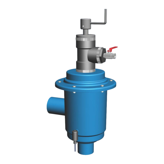
1.2 General Description & Filter Assembly The MSAF semi automatic self-cleaning filter enables high quality filtration at a grade of 80-3000 microns. The filter may be used to filter different types of media sources such as sewage, reservoir water, river water, lake water, and well water. The MSAF Filter contains the following parts: Inlet Flushing Chamber... -
Page 6: Theory Of Operation
1.3 Theory of Operation Pressurized water enters the filter inlet and travels through the neck of the filter to the body. The water then passes through a fine mesh screen where small contaminants are filtered out. The clean water then exits through the outlet of the filter. -
Page 7: Technical Data
1.4 Technical Data Standard Features Minimum operating pressure: 1 bar (14.5 psi) Maximum operating pressure: 10 bar (145 psi) Clean filter pressure loss: 0.1 bar (1.45 psi) Maximum working temperature: 65°C (149°F) Flushing water consumption (at minimum working pressure): 10 liter (2.64 US gallon) Filter housing material: Epoxy Coated Carbon Steel *Maximum... -
Page 8: Mechanical Hook-Up And Orientation
SECTION II INSTALLATION AND OPERATION 2.1 Mechanical Hook-Up and Orientation The positioning of the filter should be determined by the disposal of waste water and to allow easy access and removal of the filter element. The filter can rest on the inlet or outlet and can be mounted on a stand if desired. - Page 9 During the initial filling of the main pipeline, there may not be enough back- pressure downstream from the filter to allow the cleaning cycle to function properly. Therefore, it is necessary to install a valve at the outlet to be partially closed (i.e., gate valve, ball valve or butterfly valve).
-
Page 10: Maintenance
SECTION III MAINTENANCE 3.1 System Shut Off Procedure If your system is not equipped with a bypass valve or any similar other mechanism the entire system must be shut off. Precede the steps below with shutting off your pump and draining the system. 1. -
Page 11: Fine Screen Assembly Removal & Installation
3.3 Fine Screen Assembly Removal & Installation Perform the proper shut off procedure as described in "Section 3.1" before working on the fine screen assembly. Refer to Figure 4 below for help. 1. Remove the nuts and washers to the cover of the filter housing. 2. - Page 12 Figure 4: Exploded Fine Screen Assembly...
-
Page 13: Handle Assembly Removal & Installation
3.4 Handle Assembly Removal & Installation Perform the proper shut off procedure as described in "Section 3.1" before working on the handle assembly. Refer to Figure 5 below for help. 1. Release the bolt connecting the handle plug to the dirt collector stem. The metal handle and handle plug is a single piece and must be removed together. - Page 14 10. Open the outlet valve completely. 11. Gradually open the inlet valve while closing the bypass valve. 12. Check the filter assembly and its connections for leaks. 13. Spin the handle first counter-clockwise until it stops, and then clockwise to check the motion.
- Page 15 Figure 5: Exploded Handle & Dirt Collector Assembly...
-
Page 16: Individual Parts Breakdown
3.6 Individual Parts Breakdown Please note that some of the following parts may not be sold individually and can only be purchased as a set or assembly. Figure 6: Individual Parts Breakdown... - Page 17 Description Handle Screw O ring number 211 "T" connection (flushing chamber) O ring number 226 Body Cover Body Screw O Ring number 230 Dirt collector Bushing Dirt Collector Suction Nozzle Dirt Collector Plug Body Hydraulic Sealing Body Housing Body Outlet Pressure Indicator Body Inlet 1/4"...
Need help?
Do you have a question about the Tekleen MSAF and is the answer not in the manual?
Questions and answers