Table of Contents

Subscribe to Our Youtube Channel
Related Manuals for Jupiter Avionics JA95-N22


Summary of Contents for Jupiter Avionics JA95-N22
- Page 1 JA95-N22 Audio Controller - Flight Crew - NVG Installation and Operating Manual Rev. B Jupiter Avionics Corporation 1959 Kirschner Road Kelowna BC Canada V1Y 4N7 Tel: 778-478-2232 Toll-Free: 855-478-2232 www.jupiteravionics.com...
- Page 2 All rights reserved Jupiter Avionics Corporation (JAC) permits a single copy of this manual to be printed or downloaded for the express use of an installing agency. Any such electronic or printed copy of this manual must contain the complete text of this copyright notice.
-
Page 3: Table Of Contents
JA95-N22 Audio Controller - Flight Crew - NVG Installation and Operating Manual Table of Contents SECTION 1 - DESCRIPTION ............................1 System Overview .............................. 1 Features Overview ............................1 Inputs and Outputs ............................2 1.3.1 Inputs ................................ 2 1.3.2 Outputs ..............................2 1.3.3... - Page 4 JA95-N22 Audio Controller - Flight Crew - NVG Installation and Operating Manual Transmit Annunciator - TX .......................... 17 Transmit Selector ............................17 VOX Threshold Control ..........................18 CALL Annunciator ............................18 (10) ICS Volume Control ........................... 18 (11) ...
-
Page 5: Section 1 - Description
The JA95-N22 Audio Controller - Flight Crew - NVG can be used in a standalone configuration or a star configuration to prevent the loss of the entire system due to the failure of one controller. It provides a passive emergency mode that directs the primary user (pilot) to the COM1 transceiver, NAV1 receiver and Direct Audio receiver. -
Page 6: Inputs And Outputs
JA95-N22 Audio Controller - Flight Crew - NVG Installation and Operating Manual Inputs and Outputs Refer to the JA95-N22 connector maps for the mating connector designators and pin assignments for the input and output signals. 1.3.1 Inputs Name Type ALERT ENABLE... -
Page 7: Specifications
JA95-N22 Audio Controller - Flight Crew - NVG Installation and Operating Manual Specifications 1.4.1 Electrical Specifications Power Input Primary nominal voltage 28 Vdc Secondary nominal voltage 14 Vdc Maximum voltage 32.2 Vdc Minimum voltage 10.2 Vdc Emergency voltage 9.0 Vdc Input current at 28 Vdc ≤... - Page 8 JA95-N22 Audio Controller - Flight Crew - NVG Installation and Operating Manual Output Load Phone load 600 Ω ±10% Transceiver Microphone load 150 Ω ±10% CVR load 5000 Ω ±10% Receive Composite Audio load 600 Ω ±10% Intercom Tie Line type 1 rated load 2000 Ω...
-
Page 9: Mechanical Specifications
Installation kit part number INST-JA95 1.4.3 Environmental Specifications The JA95-N22 Audio Controller - Flight Crew - NVG has been tested to the environmental conditions listed in the Environmental Qualification Form in Appendix B of this manual. 1.4.4 Flammability of Materials The JA95-N22 complies with the requirements of RTCA/DO-160G Sec 26.3.3 'Flammability', through equivalent... -
Page 10: Section 2 - Installation
The conditions and tests for CAN TSO and FAA TSO approval of the JA95-N22 are minimum performance standards. Those installing the JA95-N22, on or in a specific type or class of aircraft, must determine that the aircraft installation conditions are within TSO standards. The JA95-N22 may be installed only by following the applicable airworthiness requirements. -
Page 11: Mechanical Installation
2.4.3 Mechanical Installation The JA95-N22 can be mounted in any attitude and location with adequate space for the front panel and sufficient clearance for the connector and wiring harness. It requires no direct cooling. 2.4.4... -
Page 12: Adjustments And Configuration Using Procs
All the JA95-N22 internal adjustments are set from the configuration program ProCS™. Configuration data is sent to the JA95-N22 via the front panel connector (♫/io), using the configuration program and CAB-USB-0002 and JA99 Configuration Cables. For full information on the configuration process, refer to the ProCS™... - Page 13 JA95-N22 Audio Controller - Flight Crew - NVG Installation and Operating Manual 2.5.2.2 Radios The Radios window is used to define the radios for the transceivers and receivers. 2.5.2.3 Receive Levels The receive and direct audio input level of each of the eleven RX and the DIRECT AUDIO inputs can be adjusted from 1 to 10 Vrms.
- Page 14 JA95-N22 Audio Controller - Flight Crew - NVG Installation and Operating Manual The Receive Audio Detector threshold can be adjusted from -36 to -12 dB of rated input level. (Default -24 dB) The level of the receive composite audio output (RX COMP OUT) can be adjusted from 0.25 to 2.5 Vrms.
- Page 15 WARNING: The internal audio alert is intended only to supplement, NOT replace, Audio Files The JA95-N22 has standard audio signals for the alert, and the audio files window allows this signal to be customized with other recordings during the configuration process.
- Page 16 JA95-N22 Audio Controller - Flight Crew - NVG Installation and Operating Manual 2.5.2.8 Audio Muting (During Transmit) When the Mute RX Audio check box is checked the Receive Audio is muted during transmit. (Default checked) When the Mute ICS Audio check box is checked the ICS Audio is muted during transmit.
- Page 17 (Default not checked) 2.5.2.14 Connector Maps This section contains connector maps and interconnects that are automatically generated to show changes that affect the installation of the JA95-N22, such as switch labels and voltages. See section 2.7.1. Rev B...
-
Page 18: Other Configuration Features
2.5.3 Other Configuration Features The model number, serial number and check sum of the JA95-N22 Audio Controller - Flight Crew - NVG can be entered and viewed in the Comments pane of the JA95-N22 Product Information Window for future reference. -
Page 19: Section 3 - Operation
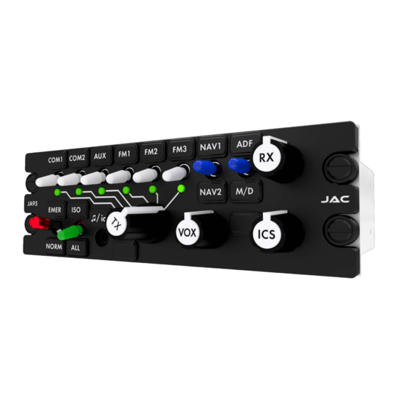
JA95-N22 Audio Controller - Flight Crew - NVG SECTION 3 – OPERATION Introduction This section contains the operating instructions for the JA95-N22. Front Panel Controls Note: The 15 legends and two annunciators are removable and may be replaced with custom ordered parts. -
Page 20: Transceiver Switches
JA95-N22 Audio Controller - Flight Crew - NVG Installation and Operating Manual Transceiver Switches These are six white two-position toggle switches. When a switch is set to the ‘up’ position, audio from the associated transceiver is routed to the phones. -
Page 21: Ics Isolation Switch (Iso/All)
JA95-N22 Audio Controller - Flight Crew - NVG Installation and Operating Manual ICS Isolation Switch (ISO/ALL) This is a green two-position toggle switch labeled ISO/ALL that enables or disables the ICS T Line. Refer to the JA95-N22 Block Diagram in Appendix A. -
Page 22: Vox Threshold Control
Note: Numbers in parentheses refer to the front panel controls shown in section 3.2. The JA95-N22 is in Normal mode when the front panel EMER / NORM switch (4) is in the NORM position and suitable electrical power is supplied to the unit. -
Page 23: Receiving
3.3.2 Receiving When the JA95-N22 receives an incoming transmission on a transceiver or receiver that has been selected, either by the white transceiver receive switches (1) or the transmit selector (8), the incoming audio will be directed to the user’s phones. -
Page 24: Emergency Operation Mode
CVR. The pilot's microphone and transmit key are connected to the COM1 transceiver. No other function in the JA95-N22 will operate when power is lost. All indicator LEDs, legends and annunciators will be dark. -
Page 25: Appendix A - Installation Drawings
Appendix A - Installation Drawings Introduction The drawings necessary for installation and troubleshooting of the JA95-N22 Audio Controller - Flight Crew - NVG are in this Appendix, as listed below. Note: A fully customized set of Connector Maps and Interconnects can be created using the ProCS™... - Page 26 06-05-18 CHECKED TITLE Audio Controller - Flight Crew - NVG Equipment Block Diagram CONFIGURABLE FUNCTION 06-05-18 APPROVED NCAGE CODE PART NO. SHEET L00N3 JA95-N22 DOC NO. JA95-N22 Equipment Block Diagram Rev A.dwg JUPITER AVIONICS TEMPLATE AUTOCAD LANDSCAPE SIZEA REV B.DWT...
- Page 27 Audio Controller - Flight Crew - NVG P1 Connector Map APPROVED 05-11-15 NCAGE CODE PART NO. SHEET L00N3 JA95-N22 DOC NO. CONFIDENTIAL & PROPRIETARY JA95-N22 Connector Map Rev A.dwg TO JUPITER AVIONICS CORP. JUPITER AVIONICS TEMPLATE AUTOCAD PORTRAIT SIZEA REV B.DWT...
- Page 28 Audio Controller - Flight Crew - NVG P2 Connector Map APPROVED 05-11-15 NCAGE CODE PART NO. SHEET L00N3 JA95-N22 DOC NO. CONFIDENTIAL & PROPRIETARY JA95-N22 Connector Map Rev A.dwg TO JUPITER AVIONICS CORP. JUPITER AVIONICS TEMPLATE AUTOCAD PORTRAIT SIZEA REV B.DWT...
- Page 29 Audio Controller - Flight Crew - NVG P3 Connector Map APPROVED 05-11-15 NCAGE CODE PART NO. SHEET L00N3 JA95-N22 DOC NO. CONFIDENTIAL & PROPRIETARY JA95-N22 Connector Map Rev A.dwg TO JUPITER AVIONICS CORP. JUPITER AVIONICS TEMPLATE AUTOCAD PORTRAIT SIZEA REV B.DWT...
- Page 30 TITLE Audio Controller - Flight Crew - NVG Interconnect Notes APPROVED 05-12-15 NCAGE CODE PART NO. SHEET L00N3 JA95-N22 DOC NO. CONFIDENTIAL & PROPRIETARY JA95-N22 Interconnect Rev A.dwg TO JUPITER AVIONICS CORP. JUPITER AVIONICS TEMPLATE AUTOCAD PORTRAIT SIZEA REV B.DWT...
- Page 31 + 5 VDC LIGHTS PREPARED 05-11-15 CHECKED TITLE Audio Controller - Flight Crew - NVG J1 Interconnect APPROVED 05-12-15 NCAGE CODE PART NO. SHEET L00N3 JA95-N22 DOC NO. JA95-N22 Interconnect Rev A.dwg JUPITER AVIONICS TEMPLATE AUTOCAD PORTRAIT SIZEA REV B.DWT...
- Page 32 POWER GROUND AIRFRAME GROUND PREPARED 05-11-15 CHECKED TITLE Audio Controller - Flight Crew - NVG J2 Interconnect APPROVED 05-12-15 NCAGE CODE PART NO. SHEET L00N3 JA95-N22 DOC NO. JA95-N22 Interconnect Rev A.dwg JUPITER AVIONICS TEMPLATE AUTOCAD PORTRAIT SIZEA REV B.DWT...
- Page 33 FRONT PANEL MUSIC LEFT PREPARED 05-11-15 CHECKED TITLE Audio Controller - Flight Crew - NVG Interconnect Options APPROVED 05-12-15 NCAGE CODE PART NO. SHEET L00N3 JA95-N22 DOC NO. JA95-N22 Interconnect Rev A.dwg JUPITER AVIONICS TEMPLATE AUTOCAD PORTRAIT SIZEA REV B.DWT...
- Page 34 22 AWG CHASSIS GROUND PREPARED 05-11-15 CHECKED TITLE Audio Controller - Flight Crew - NVG Interconnect Options APPROVED 05-12-15 NCAGE CODE PART NO. SHEET L00N3 JA95-N22 DOC NO. JA95-N22 Interconnect Rev A.dwg JUPITER AVIONICS TEMPLATE AUTOCAD PORTRAIT SIZEA REV B.DWT...
- Page 35 ANGLES: 0.5 DEG SHEET 06-04-18 NCAGE CODE PART NO. APPROVED L00N3 JA95-N22 CONFIDENTIAL & PROPRIETARY DOC. NO. MATERIAL: TO JUPITER AVIONICS CORP. JA95-N22 Mechanical Installation Rev B.SLDDRW FINISH: DRAWING NOT TO SCALE JUPITER AVIONICS TEMPLATE SOLIDWORKS PORTRAIT SIZEA REVB .DRWDOT...
- Page 36 Jupiter Avionics Corporation Audio Controllers Legend Replacement Field-Replaceable Legends Extractor tool Jupiter Avionics Corporation (JAC) products have field-replaceable illuminated recess legends. This permits easy customization, and allows the same units to be used in multiple different configurations with only minimal changes.
-
Page 37: Appendix B - Certification Documents
JA95-N22 Audio Controller - Flight Crew - NVG Installation and Operating Manual Appendix B - Certification Documents Rev A Page B1... -
Page 38: B1 Airworthiness Approval
The JA95-N22 Installation Manual provides detailed installation instructions and wiring diagrams (Section 2, and Appendices A and B). Power is supplied to the JA95-N22 through an existing [ ]-Amp circuit breaker that was previously used by the original audio panel. The net electrical load is unchanged. -
Page 39: B3 Environmental Qualification Form
Refer to the JA95-N22 Maintenance Manual. 7. Removal and Replacement Information Refer to Section 2 of this manual - the JA95-N22 Installation and Operating Manual. If the unit is removed and reinstalled, a functional check of the equipment should be conducted. - Page 40 JA95-N22 Build Configuration Rev B Manufacturer’s Test Report: JA95-001 Test Report (Qualification - Final) Rev B JA95-N22 CAN-TSO Design Change Assessment (BC Rev B) Rev A Manufacturer’s Specification JA95-001 Declaration of Design and Performance Rev D and/or Other Applicable Specification:...
- Page 41 R (20 V/m CW&SW) and (150 V/m PM) Conducted R (30 mA) (See remark 3) Radio Frequency Emission 21.0 Equipment tested to Category H (See remark 3) CONFIDENTIAL AND PROPRIETARY TO JUPITER AVIONICS CORPORATION. Rev A Page 2 of 3...
- Page 42 This product is a derivative of the JA95-001. All tests were performed on the JA95-001. A similarity analysis between the two products is detailed in the Jupiter Avionics Corp. document: JA95-N22 CAN-TSO Design Change Assessment (BC Rev B) Rev A Test information can be found in the Jupiter Avionics Corp.
Need help?
Do you have a question about the JA95-N22 and is the answer not in the manual?
Questions and answers