Table of Contents
Advertisement
Quick Links
Advertisement
Table of Contents

Related Manuals for DIGITAL DELAY Mega 475

Summary of Contents for DIGITAL DELAY Mega 475
- Page 1 Mega 475 Instruction Manual - 1 -...
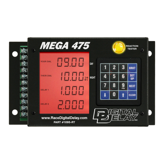
- Page 2 563-324-1046 www.RaceDigitalDelay.com Congratulations on your purchase of the Mega 475 the latest delay box from Digital Delay. The Mega 475 is the first Delay box from Digital Delay to control a digital Dial Display board. The Mega 475 can control any Digital Delay version 2 Dial Display boards, including multiple display boards and our Dual View display boards.
-
Page 3: Upgrading From A 350, 450 Or 500
Mega 350,450, or Elite 500 If you are upgrading from a Mega 350, 450 or an Elite 500 you will find the Mega 475 is similarly laid out. The Keypad is the same and the screens are laid out in the same four-line fashion. -
Page 4: Table Of Contents
MEGA 475 Table of Contents Upgrading from a 350, 450 or 500……..………..Page 3 Basic Overview of the Mega 475…..……….……..Page 9 Getting Started (Basics for Keypad and Screen)……Page 10 Initial Setup of the Mega 475...….…..…...………..Page 11 Setting Bracket and Pro Mode Screens…………….. Page 11 Bracket Mode Screens Dial-in and Delay……………………..……. - Page 5 Shift Control……..……………..………..Page 39 Dial Board Control…….……......Page 43 Driver’s Reaction Tester……......Page 45 Replay Tach……..……………..………..Page 47 Push-button Inputs….…..………..………..Page 49 Button 1…………………….………. Page 49 Button 2…………………….………. Page 52 Tap Button……...………….….…… Page 53 Line Lock Button…….………….…. Page 54 Additional Button Functions Chart..Page 55 Wiring The Terminal Strip………………………….
- Page 6 Back-up Feature……………………………. Page 62 Bypass Button……………………………..Page 62 Additional Button Functions Chart……..Page 55 Bracket Tap Up/Down Setting Tap Up/Down……..……………… Page 13 Understanding Tap Features……………….. Page 27 Additional Button Functions Chart……..Page 55 Bracket Timers Setting Timers 1 and 2…...………………… Page 15 Setting Throttle Mode …………...………..
- Page 7 Understanding Tach and Peak RPM……..Page 39 Understanding Shift Points………..……..Page 39 Understanding Shift Number……..……..Page 40 Understanding Shift Mode………..……..Page 40 Understanding Shift by Time or RPM…..Page 40 Changing the Shift Points………………….. Page 41 Testing the Shift features……..…..……..Page 42 The Reaction Tester Screen Bracket…..………………………………….
- Page 8 Pro S.L.E. Understanding the S.L.E........ Page 34 Understanding Tap Button ......Page 53 Additional Button Functions Chart……..Page 55 Pro Line Lock Setting S.F.O. Mode to 3 (Line Lock)……... Page 13 Understanding Line Lock Mode..…....Page 32 Understanding Line Lock Button……...……Page 54 Additional Button Functions Chart……..
-
Page 9: Basic Overview Of The Mega 475
The Tach also has a built-in peak RPM feature. The Replay Tach can now store up to 9 passes for later review on the screen of the Mega 475. The Replay Tach can also store any shifts made by the Mega 475. -
Page 10: Getting Started (Basics For Keypad And Screen)
Delays settings. The Bracket Screen can be returned to at any time by pressing the Bracket key (BRKT) on the keypad. This will also put the Mega 475 into Bracket Mode. The Pro Screen is the home screen for Pro Mode. The Pro Screen can be returned to at any time by pressing the Setup key followed by the Number 9 key. -
Page 11: Initial Setup Of The Mega 475
Bracket (BRKT) key. Initial Setup of the Mega 475 When the Mega 475 arrives and you turn it on, you will see the Bracket Mode Dial-In and Delay Screen. With the initial factory settings, the Mega 475 will function as a basic Crossover Delay Box, without any changes done to it. -
Page 12: Bracket Mode Screens
The Dial-In and Delay Screen Bracket Mode Screen 1 The Dial-in and Delay screen is the “home” Bracket Mode screen. Press the BRKT key to return to this screen at any time. This screen is where you enter your dial-in and delay times. -
Page 13: Special Functions Screen 1
Delay when taking two shots at the tree. The Push-button Mode controls how the Mega 475 handles the push-buttons to start a pass. The S.F.O. Mode controls what the S.F.O terminal will function as. -
Page 14: Special Functions Screen
Special Functions Screen 2 Bracket Mode Screen 3 This screen has settings for the S.L.E. (Starting Line Enhancer), P.T.S.O. (Programmable Throttle Stop Override), Timer 1 Range and Timer 2 Range. The Timer ranges adjust whether a Timer can be programmed down to a Thousandth or Hundredth of a second. -
Page 15: Timers 1 And
Timer 1 and 2 Screens Bracket Mode Screens 4 and 5 The next two screens are the 4-Stage Timer screens. All of the Timer screens are adjusted in the same way. The Timer 2 screen is only accessible when the S.F.O. mode is set to 2. -
Page 16: Shift Control
Shift Control Bracket Mode Screen 6 The Mega 475 can handle up to 5 shifts by time or RPM in a single pass. The Selection Arrows on the right side of the screen are used to show the line that is currently selected. -
Page 17: Dial Board Intensity Control
Note: To turn off the Dial Display control part of the Mega 475, set the intensity setting for both Day and Night to zero. This would be done if the Mega 475 is not connected to a Dial Display or if there is communication failure that can’t be resolved. -
Page 18: Driver's Reaction Tester
For Push-button Modes 1 – 4 release the button being held. For Push-button Mode 5 press the button connected to P.B. 1. The Mega 475 will now display your reaction time. Keep in mind that the reaction time does not directly correlate to the Delay times used on the Dial-in and Delay screen. -
Page 19: Replay Tach
Note: The Replay Tach screen can only be viewed when the engine is not running. If the engine is started while viewing the Replay Tach the Mega 475 will automatically return to the Dial-in and Delay screen. Replay Tach This is the recorded engine RPM, for the time shown on the next line. -
Page 20: Pro Mode Screens
The Pro Screen Pro Mode Screen 1 The Pro screen is the “home” Pro Mode screen. Press the SET UP key followed by the 9 key to return to this screen at any time. This screen allows you quick access to the values needed most for Pro light racing. -
Page 21: Timers 1 And
Timer 1 and 2 Screens Pro Mode Screens 2 and 3 The next two screens are the 4-Stage Timer screens. All of the Timer screens are adjusted in the same way. The Timer 2 screen is only accessible when the S.F.O. mode is set to 2. -
Page 22: Shift Control
Shift Control Pro Mode Screen 4 The Mega 475 can handle up to 5 shifts by time or RPM in a single pass. The Selection Arrows on the right side of the screen are used to show the line that is currently selected. -
Page 23: Driver's Reaction Tester
To practice, press and hold down the push-button connected to the P.B. 1 terminal. If the Mega 475 is in Push-button Mode 5, press the button connected to P.B. 2. The screen will go blank. Then when the screen displays eights on the screen, release the button or for Push-button Mode 5 press the button connected to P.B. -
Page 24: Replay Tach
Note: The Replay Tach screen can only be viewed when the engine is not running. If the engine is started while viewing the Replay Tach the Mega 475 will automatically return to the Pro screen. Replay Tach This is the recorded engine RPM, for the time shown on the next line. -
Page 25: Dial-In And Delays
Delay 1 time will be used as the delay amount for the Transbrake. The Mega 475 also allows a second hit at the tree. This is where the Delay 2 time is used. Depending on the Push-button Mode, the second hit at the tree can be done with the same button connected to P.B. - Page 26 The How Late time is displayed on line 4 of the Tap / Multi Tap & How Late screen. Note: No Delay Box including the Mega 475 can tell which hit at the tree is better, only which hit at the tree reached zero first.
-
Page 27: Special Functions Screen 1
Understanding the Special Functions Screen 1 Tap Amount The Tap amount is shown by right two digits on the top line. This value will be used for both the Tap Up amount and the Tap Down amount. Any number from .000 to .099 can be used for the Tap amount. - Page 28 Mode is set to either 2 or 3. In either of these two cases the Mega 475 is set up to take two shots at the tree. When both Delay 1 and Delay 2 are counting down at the same time, a How Late time is automatically generated at the release of the Transbrake solenoid.
- Page 29 Note: The Mega 475 updates the Tap and How Late information each pass. So there is no need to manually clear the Tap Count and How Late. If you want to manually clear the Tap Count and How Late information, the Selection Arrows need to be on the second line, and then press the CLEAR key.
- Page 30 When the button is released the delay time starts counting down. If the button is pressed and released again before the Transbrake releases the Mega 475 will restart the full delay sequence again. This can be very helpful if you flinch and let go of the push-button before the tree comes on.
- Page 31 When the button connected to the P.B. 1 input is pressed, the Cross time starts counting down. If the button is pressed again the again before the Transbrake releases the Mega 475 will restart the full delay sequence again. This can be very helpful if you flinch and press the push-button before the tree comes on.
- Page 32 S.F.O. Mode S.F.O. stands for Selectable Function Output. This mode is used to control what the function of the S.F.O. output is. There are five different S.F.O. modes (1-5) listed below. 1) S.F.O. Mode 1 – Sets the S.F.O. output terminal to function as a Starting Line Enhancer (S.L.E.).
-
Page 33: Special Functions Screen
S.L.E. to activate. Once activated, the S.L.E. stays on until the Transbrake Delay time is counting down. While the Transbrake Delay time is counted down the Mega 475 compares the S.L.E time to the remaining Delay time. When the Delay time becomes less than the S.L.E. - Page 34 Pro Mode S.L.E. In Pro Mode the S.L.E. can only be activated by pressing the Tap-Down button before the Transbrake is engaged. When activated, the S.L.E. will close the Throttle Stop. This allows the driver to push the gas pedal to wide open throttle position and have the engine rev only to the preset RPM level.
- Page 35 Stages 2 and 4 of Timer 1. After the Transbrake releases, the Mega 475 waits a quarter of a second before enabling the P.T.S.O. This is to ensure that a late Delay Tap Down is not registered as a P.T.S.O.
-
Page 36: Timers
Understanding the Timers Both the Timers in the Mega 475 are 4-Stage Timers. The 4-Stage Timers are used to control down-track events, using a pre-programmed time. Some examples of what a 4- Stage Timer may control are Throttle Stops, Nitrous solenoids, a Lockup Converter, Electrically controlled shocks, and Lean-out Valves. - Page 37 turned on. Stage 2 would be how long the Nitrous stayed on. If it is desired to have the Nitrous on for the rest of the pass, enter a Stage 2 time greater than the vehicle’s ET. The Chart below shows the operation of the 4-Stage Timer in relation to the release of the Transbrake solenoid.
-
Page 38: Throttle Mode
Understanding Throttle Mode The Throttle Mode is used to control whether the output will supply 12 Volts (On) or remove 12 Volts (Off) for the Stages. Each 4-Stage Timer has a Throttle Mode associated with it. The Throttle Mode has two settings shown as on/off/on/off or off/on/off/on. - Page 39 The only invalid RPM setting is zero. If the next Shift Point is a Time, the Mega 475 checks to make sure that the time setting for the Shift Point is greater than the amount of time that has gone by since the release of the Transbrake.
- Page 40 “HI” and “LO” settings. Shift by RPM or Time (Up Arrow key) The Mega 475 can handle up to five shifts on each pass. These five shifts can be made by time, RPM, or a combination of both. To select if a shift will be by time or RPM, while the selection arrows are on line 4, press and release the Up Arrow key.
- Page 41 pressed and released the Shift will toggle between either an RPM or a Time shift. On line two, as the Shift is toggled between RPM and Time, the text TIME and a decimal will be shown for a Time shift or the text RPM for an RPM shift. Changing the Shift Points After making sure the correct Shift Number and Shift Mode has been selected, the Shift Point can be adjusted in...
- Page 42 It should have 12 Volts when the Shift Output Mode is set to LO and zero Volts when the Shift Output Mode is set to HI. If the Mega 475 passes the first test, move onto the second test. If the output does not change, check to see if the fuse for the shift output is good.
- Page 43 The shifter should move, and hold for four tenths of a second, when the RPM reaches 3000. After the four tenths of a second the Shifter should release and the Mega 475 will move on to the second Shift Point. If all three tests pass, all of the Mega 475 shift features are working.
- Page 44 Error Messages In the event of a communication error between the Mega 475 and the Dial Display board, the bottom line on the Mega 475 screen will flash between three dashes and an error code number. E-01: A “No Board” error code of 1 shown as E-01 on the screen, means the Mega 475 cannot detect the Dial Display board.
- Page 45 If you take more than one practice shot while in the Driver’s Reaction Tester, line 2 will display the average reaction time. If the Mega 475 is in P.B. Mode 2 the button connected to the P.B. 2 terminal can also be used to practice with.
- Page 46 exit the Driver’s Reaction Test Mode after 30 seconds of inactivity. Each time a push-button is pressed for a practice hit, the 30 second timer resets. The Driver’s Reaction Tester can also be used to check different buttons and button locations for consistency and speed.
- Page 47 Replay Tach The Mega 475 has a built-in Replay Tach that can store 9 passes. When the Mega 475 records a pass, the engine RPM is recorded every hundredth of a second for fifteen seconds after the Transbrake releases. After a pass has been recorded and the engine is turned off the pass can be reviewed on the screen of the Mega 475.
- Page 48 When you press the Clear key the time will go blank indicating the Mega 475 is ready for you to enter the time you want to go directly to. All four digits must be entered.
- Page 49 What the primary, second, and third function of each button is, depends on whether the Mega 475 is in Bracket or Pro Mode and what the Push-button Mode is. Each button is listed below individually to explain their functions depending on these conditions.
- Page 50 P.B. Mode Set to 2 Uses two push-buttons, one for each Delay time. With Button 1 starting the Crossover/Delay 1 time and Button 2 starting the Delay 2 time. The main benefit of this setting is, it allows two shots at the tree, in case you missed the tree with your first release.
- Page 51 Crossover/Delay 1 time. If the button is pressed again the Mega 475 will start counting down the full Crossover/Delay 1 time again. This is helpful if the driver flinches (presses the button before the top yellow comes on).
- Page 52 Button 2 When in Bracket Mode P.B. Mode is Set to 2 Button 2 is only used to activate Delay 2. Each time Button 2 is pressed the Transbrake solenoid is engaged and the Delay 2 time value is loaded into a counter. When the button is then released the counter starts timing down.
- Page 53 P.B. Mode is Set to 5 The first function for Button 2 is to set the Transbrake solenoid. When the button is pressed the Transbrake will engage, however on the release of the button the timing is started. There is no second or third function for Button 2 in Pro Mode.
- Page 54 Line Lock Button Settings When in Bracket Mode Any P.B. Mode The first function for the Line Lock button is to activate the Line Lock solenoid(s) for a burn-out. This also arms the Replay Tach at the same time. The second function for Line Lock button is Tap Up, allowing time to be added to the first delay started.
- Page 55 - 55 -...
- Page 56 To figure out your total current load, add up the individual current draw of each device connected to an output on the Mega 475. Then use the list below to see what gauge power wire you need.
- Page 57 S.F.O. terminal and the other wire from the device needs to be connected to ground. Note: If the device to be controlled needs Ground, instead of +12 Volts, an additional relay will need to be wired between the Mega 475 and the device, page 61. - 57 -...
- Page 58 Note: If the device to be controlled needs Ground, instead of +12 Volts, an additional relay will need to be wired between the Mega 475 and the device page 61. Shift Terminal: The Shift terminal is a dedicated output for use with a Shift solenoid.
- Page 59 Shift solenoid to a ground. It is recommended that the wire going from the Mega 475 shift terminal to the shift solenoid be separated from all other wires to eliminate cross talk between the wires. If all wires are bundled together undesirable results may occur.
- Page 60 Tach Terminal: Connect the Tach terminal to the tach output on the ignition. The Tach terminal must be connected for proper operation of the Mega 475, when shifting by RPM or utilizing the Replay Tach feature. - 60 -...
- Page 61 Additional Wiring Help Wiring Three Wire Push-buttons Most push-buttons only have two wires. If your push-button has three wires you will only need to use two of them. The two wires are the Common ( C ) and the Normally Open ( N O ). The Normally Closed ( N C ) wire is not used.
- Page 62 To wire in a bypass button take one wire from your button and connect it to the Power terminal on the Mega 475. Then connect the other wire from the button to the Transbrake terminal on Mega 475.
- Page 63 Recommended Wire Gauge for Current A Voltage drop is the amount of voltage lost through a wire. Example of a 2 Volt drop would be if one end of the wire has 12 Volts and the other end has 10 Volts. Voltage drops are caused by undersized wiring in the vehicle, resulting in solenoids not getting the needed voltage for proper operation.
- Page 64 Before mounting the Mega 475, place the box in the desired location and check the legibility of the display in both day and night conditions.
- Page 65 Dial Display Board There are three wires a Blue, Purple, and a Tan coming out of the Mega 475 on the top right side. The Blue and Purple are used for data while the Tan is used to control whether the Day or Night intensity is selected.
- Page 66 Digital Delay Inc. and Digital Delay Electronics, Inc against damages, claims, and expenses arising out of subsequent sales of or use of Digital Delay Inc. and Digital Delay Electronics, Inc products, or products containing components manufactured by Digital Delay Electronics, Inc. and based upon personal injuries,...
Need help?
Do you have a question about the Mega 475 and is the answer not in the manual?
Questions and answers