Table of Contents
Advertisement
Quick Links
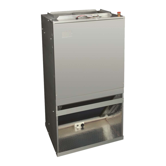
FMA4X, FMA4P
Apartment Fan Coil Unit
NOTE: Read the entire instruction manual before starting the installation.
SAFETY CONSIDERATIONS
Improper installation, adjustment, alteration, service, maintenance, or
use can cause explosion, fire, electrical shock, or other conditions which
may cause death, personal injury or property damage. Consult a
qualified installer, service agency, or your distributor or branch for
information or assistance. The qualified installer or agency must use
factory-authorized kits or accessories when modifying this product.
Refer to individual instructions packaged with kits or accessories when
installing.
Follow all safety codes. Wear safety glasses, protective clothing, and
work gloves. Use quenching cloth for brazing operations. Have a fire
extinguisher available. Read these instructions thoroughly and follow all
warning or cautions included in literature and attached to the unit.
Consult local building codes and the current editions of the National
Electrical Code (NEC) NFPA 70.
In Canada, refer to the current editions of Canadian Electrical Code CSA
C22.1.
Recognize safety information. This is the safety alert symbol
you see this symbol on the unit and in instructions or manuals, be alert to
the potential for personal injury. Understand the signal words
DANGER, WARNING, and CAUTION. These words are used with the
safety alert symbol. DANGER identifies the most serious hazards which
will result in severe personal injury or death. WARNING signifies
hazards which could result in personal injury or death. CAUTION is
used to identify unsafe practices, which may result in minor personal
injury or product and property damage. NOTE is used to highlight
suggestions which will result in enhanced installation, reliability, or
operation.
INTRODUCTION
FMA4X, FMA4P Fan Coils are designed with application flexibility in
mind and are suitable for closet and flush mount installations. Units are
available with field-installed electric heat with circuit breaker. Units are
used indoors as the fan coil for split-system heat pumps or air
conditioners. The FMA4P uses a refrigerant piston metering device and
a 3 Speed PSC Motor. FMA4X uses a TXV and a 5 speed multi-tap
ECM motor for efficiency. Units are available in 18,000 through 36,000
Btuh nominal cooling capacities.
Field-installed heaters are available in 5, 7.5, and 10 kW sizes. The coil
is equipped with sweat-type connections and is vapor-charged with dry
nitrogen. The casing is fully insulated to meet applications in
conditioned space. Additional insulation is required if the unit is
installed in unconditioned space.
NOTE: Nuisance sweating may occur if the unit is installed in a humid
location with low airflow.
Units are designed for upflow applications only. Local codes may limit
this free-air-return type unit to installation in single-level applications.
INSTALLATION
Check Equipment
Unpack unit and move to final location. Remove carton, taking care not
to damage unit. Remove protective sheet metal from the base of the unit,
if equipped. Inspect equipment for damage prior to installation. File
claim with shipping company if shipment is damaged or incomplete.
Installation Instructions
. When
WARNING
!
ELECTRICAL OPERATION HAZARD
Failure to follow this warning could result in personal injury or death.
Before installing or servicing the unit, always turn off all power to unit.
There may be more than one disconnect switch. Turn off accessory
heater power if applicable. Lock out and tag switch with a suitable
warning label.
WARNING
!
EXPLOSION HAZARD
Failure to follow this warning could result in death, serious personal
injury, and/or property damage.
Never use air or gases containing oxygen for leak testing or operating
refrigerant compressors. Pressurized mixtures of air or gases containing
oxygen can lead to an explosion.
!
CUT HAZARD
Failure to follow this caution may result in personal injury.
Sheet metal parts may have sharp edges or burrs. Use care and wear
appropriate protective clothing, safety glasses and gloves when
handling parts.
Locate rating plate on unit. It contains information needed to properly
install unit. Check rating plate to be sure unit matches job specifications.
A front access panel is provided, which permits access to blower
assembly and electrical controls for removal and servicing.
NOTE: Minimum clearance of 21" (533 mm) is required in front of
access panel for servicing only. Installation clearance from combustible
materials is 0" (0 mm) from cabinet and supply-air duct (plenum
included). Make sure there is adequate space on top of unit for
refrigerant line connections and on bottom of unit for condensate trap
(Fig. 1
and
Fig.
2).
Mount Fan Coil
Fan Coil Mounting Options
The fan coil comes standard with two different options for mounting:
wall mount or frame mount. Both mounting options require the unit to be
level from side to side and from front to back in order to allow
condensate to properly drain from the unit. Failure to do this will result
in condensate leaking out from the unit, potentially causing structural
damage to the surrounding support structures, drywall, carpet, etc.
around the unit. Also, both mounting structures require the ability to
accommodate a minimum of load of 150 pounds. Failure to do this will
cause damage to the support structure and potentially damage the unit.
CAUTION
Advertisement
Table of Contents

Related Manuals for Tempstar FMA4X


Summary of Contents for Tempstar FMA4X
- Page 1 The FMA4P uses a refrigerant piston metering device and access panel for servicing only. Installation clearance from combustible a 3 Speed PSC Motor. FMA4X uses a TXV and a 5 speed multi-tap materials is 0" (0 mm) from cabinet and supply-air duct (plenum ECM motor for efficiency.
-
Page 2: Frame Mount
FMA4X, FMA4P: Installation Instructions 1. Remove the wall mounting bracket from the back of the unit by removing one screw which attaches the bracket to the fan coil. NOTE: Discard the screw after you have removed the wall mounting bracket. -
Page 3: Ductwork Specifications
Refer to AHRI ratings to check if your combination can use the piston shipped with the unit or requires an accessory TXV. FMA4X are provided with a factory installed TXV. Ductwork Specifications Connect supply-air duct over 3/4" (19 mm) flange provided on supply-air opening. -
Page 4: Condensate Drain
FMA4X, FMA4P: Installation Instructions SECONDARY PRIMARY A13092 Fig. 5 – Transformer Connections NOTE: Before proceeding with electrical connections, make certain that voltage, frequency, and phase correspond to that specified on rating plate. Also, check to be sure that the service provided by utility is sufficient to handle additional load imposed by this equipment. -
Page 5: Sequence Of Operation
(units with ECM motor will have blower off-delay based on motor speed To change the fan speed on model FMA4X: tap selection). • At the motor connection plug connect the green wire to the desired... -
Page 6: Cut Hazard
(CONTROL) (CONTROL) 1 2 3 4 5 ORANGE YELLOW A11048 Fig. 8 – FMA4X ECM Motor Speed Taps A150159 Fig. 7 – Wiring Layout Heat Pump Unit CAUTION (Cooling and 2-Stage Heat) CUT HAZARD Failure to follow this caution may result in personal injury. - Page 7 - NOTES: Shaded boxes represent airflow outside the required 300-450 CFM/ton. Airflow based upon dry coil at 230V with no electric heat and factory-approved filter. For FMA4X airflow at 208V is approximately the same as 230V because the multi-tap ECM motor is a constant torque motor.
Need help?
Do you have a question about the FMA4X and is the answer not in the manual?
Questions and answers