Table of Contents
Advertisement
Quick Links
Published 10/04
OPERATOR'S MANUAL
This Operator's Manual is an integral part of the safe operation
of this machine and must be maintained with the unit at all
times. READ, UNDERSTAND, and FOLLOW the Safety and
Operation Instructions contained in this manual before
operating the equipment.
73747 130TH ST
ZEARING IA 50276
641-487-7608
INFO@NESSAINC.COM
WWW.NESSAINC.COM
Schulte Industries Ltd.
P.O. Box 70
Englefeld Saskatchewan Canada S0K 1N0
Tel. (306)287-3715
Fax. (306)287-3355
Parts Fax. (306)287-4066
Email: info@schulte.ca
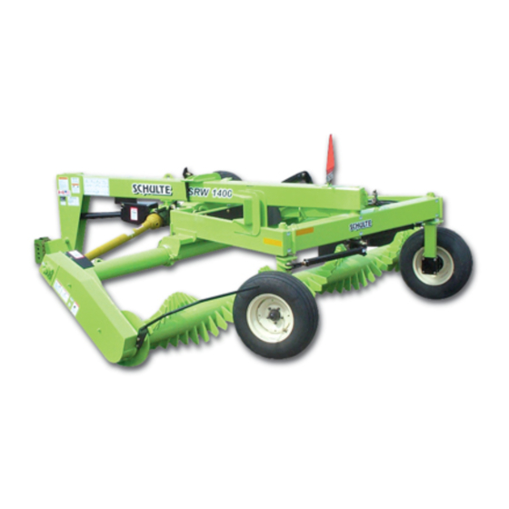
SRW1400
Pivoting Rock Windrower
S/N range R20000381411 to R20000420411 inclusive
©
2004
Alamo Group Inc.
Part No. R200-010C
$0.00
Advertisement
Chapters
Table of Contents

Related Manuals for Alamo Schulte SRW1400

Summary of Contents for Alamo Schulte SRW1400
- Page 1 Operation Instructions contained in this manual before operating the equipment. 73747 130TH ST ZEARING IA 50276 641-487-7608 INFO@NESSAINC.COM WWW.NESSAINC.COM Schulte Industries Ltd. P.O. Box 70 Englefeld Saskatchewan Canada S0K 1N0 Tel. (306)287-3715 Fax. (306)287-3355 Parts Fax. (306)287-4066 Email: info@schulte.ca © 2004 Alamo Group Inc. $0.00...
- Page 2 Read and understand the complete Warranty Statement found in this Manual. Fill out the Warranty Registration Form in full and return it to Alamo within 30 Days. Make certain the Serial Number of the Machine is recorded on the Warranty Card and on the Warranty Form that you retain.
- Page 3 DEALER’S PREDELIVERY SERVICE GUIDE for the SCHULTE SRW1400 DETAILS OF ITEMS LISTED BELOW ARE COVERED IN THIS OPERATOR’S MANUAL ____ Shipping damage corrected ____ Set up machine as outlined in the shipping instructions attached to these instructions. ____ Check that all safety decals are in good condition, replace if necessary.
-
Page 4: Table Of Contents
Lubrication ............................. 5-6 Lubrication Gearbox ..........................5-6 Grease Schedule ........................... 5-7 Windrower Frame ..........................5-7 Drive Chain ............................. 5-8 Storage ..............................5-8 Ramlock Disassembly Procedure ......................5-8 Schulte is registered trademark of Alamo Group Inc. © 2003 Alamo Group Inc. - Page 5 SAFETY SECTION Safety Section 1-1 © 2003 Alamo Group Inc.
- Page 6 Serious injury or death may occur unless care is taken to follow the warnings and instructions stated in the Safety Messages. Always use good common sense to avoid hazards. (SG-2) SRW1400 10/04 Safety Section 1-2 © Alamo Group Inc. 2004...
- Page 7 Operate the Tractor controls from the tractor seat only. (SG-9) DANGER! Never allow children or other persons to ride on the Tractor or Implement. Falling off can result in serious injury or death. (SG-10) SRW1400 10/04 Safety Section 1-3 © Alamo Group Inc. 2004...
- Page 8 The operator and all support personnel should wear hard hats, safety shoes, safety glasses, and proper hearing protection at all times for protection from injury including injury from items thrown by the equipment. (SG-16) SRW1400 10/04 Safety Section 1-4 © Alamo Group Inc. 2004...
- Page 9 Implement. (SG-20) Always read carefully and comply fully with the manufacturers instructions WARNING! when handling oil, solvents, cleansers, and any other chemical agent. (SG-22) SRW1400 10/04 Safety Section 1-5 © Alamo Group Inc. 2004...
- Page 10 Operate the Tractor and/or Implement controls only while properly seated in the Tractor seat with the seat belt securely fastened around you. Inadvertent movement of the Tractor or Implement may cause serious injury or death. (SG- SRW1400 10/04 Safety Section 1-6 © Alamo Group Inc. 2004...
- Page 11 Tractor and perform repairs before resuming operation. Serious injury and possible death could occur from not maintaining this Implement and Tractor in good operating condition. (SG-36) SRW1400 10/04 Safety Section 1-7 © Alamo Group Inc. 2004...
- Page 12 DO NOT weld or repair rotating implement components. Welds and other repairs may cause severe vibration and/or component failure resulting in parts being thrown from the implement causing serious bodily injury. See your Authorized Dealer for proper repairs. (SGM-13) SRW1400 10/04 Safety Section 1-8 © Alamo Group Inc. 2004...
- Page 13 DANGER! Make sure the PTO shield, integral driveline shields, and input shields are is installed when using PTO-driven equipment. Always replace any shield if it is damaged or missing. (S3PT-8) SRW1400 10/04 Safety Section 1-9 © Alamo Group Inc. 2004...
- Page 14 Serious bodily injury and/or equipment failure can result from using a PTO adapter. Consult an authorized dealer for assistance if the Implement driveline does not match the Tractor PTO. (S3PT-14) SRW1400 10/04 Safety Section 1-10 © Alamo Group Inc. 2004...
- Page 15 Messages and operation instruction in each of the appropriate sections of the Tractor and Equipment Manuals. Pay close attention to the Safety Signs affixed to the Tractor and Equipment. (SG-18) SRW1400 10/04 Safety Section 1-11 © Alamo Group Inc. 2004...
- Page 16 SAFETY SRW1400 10/04 Safety Section 1-12 © Alamo Group Inc. 2004...
- Page 17 (Some shipping and handling charges may apply). Contact your Schulte dealer to order replacement decals. SRW1400 10/04 Safety Section 1-13 © Alamo Group Inc. 2004...
- Page 18 5- - 226-032 9 -- 226-084 7-- 226-148 13- 226-118 3 - - 226-154 AMBER REFLECTOR 8 - - SERIAL PLATE 16 - - 226-153 RED REFLECTOR 11 - - 226-081 SRW1400 10/04 Safety Section 1-14 © Alamo Group Inc. 2004...
- Page 19 SAFETY 15 - 226-037 14 - 226-151 17 - 226-044 18 - 226-181 19 - 226-182 21 - 226-180 20 - 226-183 22 - 226-192 SRW1400 10/04 Safety Section 1-15 © Alamo Group Inc. 2004...
- Page 20 SAFETY 24 -- 226-191 23 - 226-193 26 -- 226-323 27 -- 226-004 SRW1400 10/04 Safety Section 1-16 © Alamo Group Inc. 2004...
- Page 21 SAFETY 28 - 226-049 29 - 226-048 30 - 226-070 32- 226-317 31- 226-314 SRW1400 10/04 Safety Section 1-17 © Alamo Group Inc. 2004...
- Page 22 SAFETY 33- -226-318 34 - 226-319 10- 226-340 SRW1400 10/04 Safety Section 1-18 © Alamo Group Inc. 2004...
-
Page 23: Federal Laws And Regulations
Some regulations specify that no one under the age of 16 may operate power machinery. It is your responsibility to know what these regulations are in your own area or situation. (Refer to U.S. Dept. of Labor, Employment Standard Administration, Wage & Home Division, Child Labor Bulletin #102.) SRW1400 10/04 Safety Section 1-19 © Alamo Group Inc. 2004... -
Page 25: Introduction Section
INTRODUCTION SECTION Introduction Section 2-1... - Page 26 To place the warranty into effect, fill out the warranty card in full, giving all the requested information, and mail promptly. Be sure to give the serial number of the SRW1400. Introduction Section 2-2 SRW1400 10/04 © 2004 Alamo Group Inc.
- Page 27 3. Record the Windrower Model and Serial Numbers on the Warranty page at the front of the Operator’s Manual. Keep this as part of the permanent maintenance file for the Windrower. SRW1400 10/04 Introduction Section 2-3 © 2004 Alamo Group Inc.
-
Page 29: Assembly Section
ASSEMBLY SECTION © 2003 Alamo Group Inc. -
Page 30: Before Operations
Pin the hitch jack to the forward stub on the hitch pole and raise the hitch clevis to line up with the tractor drawbar. NEVER STAND BETWEEN THE TRACTOR AND THE ROCK WINDROWER WHILE WARNING! THE TRACTOR IS BEING BACKED TO THE HITCH SRW1400 10/04 Assembly Section 3-2 © 2004 Alamo Group Inc. -
Page 31: Leveling The Windrower
IMPORTANT: Periodically re-check the tightness of the axle plate bolts especially before transporting the machine on public roads. Remove the transport pin from the lock pin hole and return it to the storage hole on the main frame. SRW1400 10/04 Assembly Section 3-3 © 2004 Alamo Group Inc. -
Page 32: Wheel Lock Pins
(Note: these shields may also be chained.) The shields must be regularly greased and checked that they rotate freely on the driveline. Refer to the Lubrication section for greasing intervals. SRW1400 10/04 Assembly Section 3-4 © 2004 Alamo Group Inc. -
Page 33: Light Kit
Use figures 3-6 through 3-9 as a guide for final placement of the wiring harness and the wire ties. SRW1400 10/04 Assembly Section 3-5 © 2004 Alamo Group Inc. -
Page 34: Pre Customer Delivery Checklist
8. Is machine equipped with proper operator protection? 9. Is drum rotation correct? Are teeth hard surfaced? 10. Does implement operate smoothly at normal operating speed? Implement should not vibrate excessively. SRW1400 10/04 Assembly Section 3-6 © 2004 Alamo Group Inc. -
Page 35: Operation Section
OPERATION SECTION Operation Section 4-1 © 2003 Alamo Group Inc. - Page 36 SCHULTE SRW1400 OPERATION INSTRUCTIONS SCHULTE SRW1400 windrower is manufactured with quality material by skilled workers. The windrower is designed to windrow small to medium surface rocks, roots, stumps, and other debris in the fields. The implement is equipped with enough protective gear to prevent objects being thrown from the SRW1400 teeth, however, no shielding is 100% accurate.
- Page 37 Safety Messages. Always use good common sense to avoid hazards. (SG-2) !LEA EL PELIGRO! INSTRUCTIVO! Si no lee Ingles, pida ayuda a alguien que si lo lea para que le traduzca las medias de seguridad (SG-3) SRW1400 10/04 Operation Section 4-3 © 2004 Alamo Group Inc.
-
Page 38: Operator Requirements
NEVER knowingly allow anyone to operate this Equipment when their alertness or coordination is impaired. Serious injury or death to the operator or others could result if the operator is under the influence of drugs or alcohol. (SG-27) SRW1400 10/04 Operation Section 4-4 © 2004 Alamo Group Inc. -
Page 39: Tractor Requirements
Maintain all manufacturer equipped safety shields and guards. Always replace shields and guards that were removed for access to connect, service, or repair the tractor or windrower. Never operate the tractor PTO with the PTO master shield missing or in the raised position. SRW1400 10/04 Operation Section 4-5 © 2004 Alamo Group Inc. -
Page 40: (2.3) Tractor Horsepower
If the front end is too light, add weight until a minimum of 20% total weight is reached on the front tires. Front weights and weight carriers can be purchased through an authorized tractor dealership. SRW1400 10/04 Operation Section 4-6 © 2004 Alamo Group Inc. -
Page 41: (2.7) Power Take Off (Pto)
Refer to the tractor Operator’s Manual or consult an authorized dealer for instructions to change tractor tire spacing. Tire Spacing Minimum Width 60” SRW1400 10/04 Operation Section 4-7 © 2004 Alamo Group Inc. -
Page 42: Getting On And Off The Tractor
Use hand rails and steps when exiting the tractor. Be careful of your step and use extra caution when mud, ice, snow or other matter has accumulated on the steps or hand rails. Use all handrails and steps for support and never rush or jump off the tractor. SRW1400 10/04 Operation Section 4-8 © 2004 Alamo Group Inc. -
Page 43: Starting The Tractor
Always shut the Tractor completely down, place the transmission in park, and set the parking brake before you or anyone else attempts to connect or disconnect the Implement and Tractor hitches. (S3PT-15) SRW1400 10/04 Operation Section 4-9 © 2004 Alamo Group Inc. -
Page 44: (5.1) Connecting The Windrower Tongue To The Tractor
Adjust length as necessary and allow only enough slack in the chain to make a maximum turn in both directions. SRW1400 10/04 Operation Section 4-10 © 2004 Alamo Group Inc. -
Page 45: (5.2) Connecting Windrower Hydraulic Lines To The Tractor
Never work under the Implement, the framework, or any lifted compo- nent unless the Implement is securely supported or blocked up to prevent sudden or inadvertent falling which could cause serious injury or even death. (SG-14) SRW1400 10/04 Operation Section 4-11 © 2004 Alamo Group Inc. -
Page 46: (6.1) Leveling Windrower
PTO shaft. A driveline not attached correctly to the Tractor PTO shaft could slip off and result in personal injury and damage to the cutter. SRW1400 10/04 Operation Section 4-12 © 2004 Alamo Group Inc. -
Page 47: Pre-Operation Inspection And Service
Make sure all pins have cotter pins and washers. Serious injury may occur from not maintaining this Implement in good working order. (SG-21) SRW1400 10/04 Operation Section 4-13 © 2004 Alamo Group Inc. -
Page 48: (8.1) Tractor Pre-Operation Inspection/Service
Decals contain important instructions on the safe and proper use of the windrower. Maintain these important safety features on the windrower in good condition to ensure the information is available to the operator at all times. SRW1400 10/04 Operation Section 4-14 © 2004 Alamo Group Inc. - Page 49 Ensure the slip clutch shields and chain belt shield is in place and in good repair. Ensure the tractor PTO master shield is in place, lowered and in good condition. SRW1400 10/04 Operation Section 4-15 © 2004 Alamo Group Inc.
- Page 50 Inspect the windrower teeth and make sure that they are hard surfaced and that the bare tooth is not exposed. If the hard surfacing is not properly maintained, highly accelerated tooth wear will result. SRW1400 10/04 Operation Section 4-16 © 2004 Alamo Group Inc.
-
Page 51: Driving The Tractor And Windrower
Such an impact could cause the Implement and Tractor to pivot violently resulting in loss of steering control, serious injury, or even death. Never allow the Implement to contact obstacles. (S3PT-12) SRW1400 10/04 Operation Section 4-17 © 2004 Alamo Group Inc. -
Page 52: (9.1) Starting The Tractor
Always disengage the tractor differential lock when turning. When engaged the differential lock will prevent or limit the tractor from turning. During normal operating conditions, locking the differential provides no benefit and should not be used. SRW1400 10/04 Operation Section 4-18 © 2004 Alamo Group Inc. -
Page 53: (9.3) Driving The Tractor And Windrower
Raise the transport wheel. Reinstall the transport wheel lock pin. Remove the drum transport lock pin. Store the drum transport lock pin in the storage hole on the main frame. SRW1400 10/04 Operation Section 4-19 © 2004 Alamo Group Inc. - Page 54 Raising the implement exposes the drum teeth which creates a potentially serious hazard and could cause serious injury or even death from objects thrown from the drum teeth. SRW1400 10/04 Operation Section 4-20 © 2004 Alamo Group Inc.
-
Page 55: (9.4) Crossing Ditches And Steep Inclines
If too much dirt is being carried in to the windrower, reduce the working depth. Ground contact also produces a severe shock load on the windrower drive and resulting in possible damage and premature wear. SRW1400 10/04 Operation Section 4-21 © 2004 Alamo Group Inc. -
Page 56: Operating The Tractor And Windrower
Remove all foreign objects and debris. If objects are too big to remove, mark them clearly and be sure to prevent the implement from contacting them. SRW1400 10/04 Operation Section 4-22 © 2004 Alamo Group Inc. -
Page 57: (10.2) Engaging The Power Take Off (Pto)
DANGER! Make sure the PTO shield, integral driveline shields, and input shields are is installed when using PTO-driven equipment. Always replace any shield if it is damaged or missing. (S3PT-8) SRW1400 10/04 Operation Section 4-23 © 2004 Alamo Group Inc. -
Page 58: (10.3) Pto Rpm And Ground Speed
1" lower then the left leg. This is to help bring material to the surface. If large rocks are being carried into the windrow, slow the tractor rpm. SRW1400 10/04 Operation Section 4-24 © 2004 Alamo Group Inc. - Page 59 PTO and wait for all implement rotation to come to a complete stop before proceeding to raise the implement. If implement is raised to high while the unit is running there is a possibilty of damaging the driveline. SRW1400 10/04 Operation Section 4-25 © 2004 Alamo Group Inc.
-
Page 60: (10.5) Shutting Down The Implement
Use extreme care to keep feet and hands out from under the implement and clear of any pinch points when disconnecting the implement from the tractor. SRW1400 10/04 Operation Section 4-26 © 2004 Alamo Group Inc. - Page 61 5. Remove the hydraulic hoses from the tractor and secure to the windrower to prevent contact with dirt. 6. After the driveline has been removed from the tractor, place the PTO master shield back in the operating position. SRW1400 10/04 Operation Section 4-27 © 2004 Alamo Group Inc.
-
Page 62: Windrower Storage
If the implement has been exposed to such conditions, at the start of each season, and any time it is suspected that the slip clutch plates may be frozen together, readjust the slip clutch as explained in the maintenance section of this manual SRW1400 10/04 Operation Section 4-28 © 2004 Alamo Group Inc. -
Page 63: Transporting The Tractor And Windrower
Lower the wheel lock pins into the pivoting wheel assembly. Install the wedge lock into the transport cradle. NOTE: The flat edge of the wedge lock should be against the hitch pole. SRW1400 10/04 Operation Section 4-29 © 2004 Alamo Group Inc. - Page 64 In wet conditions where there is a likelihood of material collecting on WARNING! the Implement, make certain that this material is removed before travelling on public roadways. (STL-7) SRW1400 10/04 Operation Section 4-30 © 2004 Alamo Group Inc.
-
Page 65: (13.1) Transporting On Public Roadways
Consult an authorized tractor dealer for lighting kits and modifications available to upgrade the lighting on older tractor models. SRW1400 10/04 Operation Section 4-31 © 2004 Alamo Group Inc. - Page 66 Turn curves or go up or down hills only at a low speed and at a gradual steering angle. Make certain that at least 20% of the tractor’s weight is on the front wheels to maintain safe steerage. Slow down on rough or uneven surfaces. (STI-1) SRW1400 10/04 Operation Section 4-32 © 2004 Alamo Group Inc.
- Page 67 When operating in traffic always use the Tractor’s flashing warning lights and reduce your speed. Be aware of traffic around you and watch out for the other guy. (SG-19) SRW1400 10/04 Operation Section 4-33 © 2004 Alamo Group Inc.
-
Page 68: (13.2) Hauling The Tractor And Windrower
If during transport a hard braking, sharp turning, or swerving action was performed, stop at the next safe location to inspect the security of the load. SRW1400 10/04 Operation Section 4-34 © 2004 Alamo Group Inc. -
Page 69: Trouble Shooting Guide
Torque limiter slipping exces- Machine is overloaded, reduce Excessive load sively ground speed & reduce depth Adjust springs Improper adjustment Replace Plates Friction plates worn Replace Plates Oil on friction plates SRW1400 10/04 Operation Section 4-35 © 2004 Alamo Group Inc. -
Page 71: Maintenance Section
MAINTENANCE SECTION © 2003 Alamo Group Inc. -
Page 72: Nuts And Bolts
The plastic cones shielding the slip clutch and shear bolt need to be periodically/ frequently cleaned. Stop the tractor engine, disconnect the PTO shaft and remove any debris that has accumulated inside the shield. Maintenance Section 5-2 SRW1400 10/04 © 2004 Alamo Group Inc. -
Page 73: Hub And Spindles
7. Check dust seal to ensure seal rubber is positioned correctly. 8. Install the small or outer bearing. 9. Install the axle washer and castle nut on the axle. Maintenance Section 5-3 SRW1400 10/04 © 2004 Alamo Group Inc. -
Page 74: Tightening Intructions For 511 & 517 Hubs
Occasionally apply grease to the shear plates. IMPORTANT: Replacement of the shear bolt with one of any other grade or size will be considered unauthorized modification and warranty will be void. Maintenance Section 5-4 SRW1400 10/04 © 2004 Alamo Group Inc. -
Page 75: Slipclutch
Refer to the following illustration and set the height of the clutch springs as indicated. Tighten nuts following an alternating cross pattern. Check that the height is constant for all springs. Maintenance Section 5-5 SRW1400 10/04 © 2004 Alamo Group Inc. -
Page 76: Lubrication Gearbox
Gear case oil should meet the following specifications: -API Service Classifications GL-5 -Military Specification MIL-L-2105C Consult the following chart for the oil viscosity recommendations: NOTE: Use SAE 80-90Gear Oil Maintenance Section 5-6 SRW1400 10/04 © 2004 Alamo Group Inc. -
Page 77: Grease Schedule
Grease should be pumped into the bearing until it is seen purging at the clearance between the outer race and slinger. Wheel Hubs -Wheel Hubs: Yearly. Fill until grease is seen purging at the axle seals. Maintenance Section 5-7 SRW1400 10/04 © 2004 Alamo Group Inc. -
Page 78: Drive Chain
Locate the slots at either end of the barrel. The cylinder head will be removed first. Using a thin blade screwdriver, insert the blade into the end of the slot near the cylinder head and pry the retaining wire up slightly. Maintenance Section 5-8 SRW1400 10/04 © 2004 Alamo Group Inc. - Page 79 Assembly is the opposite of disassembly. Use a small amount of oil to lubricate all seals prior to assembly. Caution must be used to prevent seal damage. Maintenance Section 5-9 SRW1400 10/04 © 2004 Alamo Group Inc.
- Page 81 Schulte Industries Limited (“the manufacturer”) warrants to the original purchaser only, that in the event of any defect in material or workmanship in the Schulte SRW1400, the subject of this warranty (“the goods”) during the warranty period mentioned below the manufacturer will provide the cover specified below.
- Page 82 COVER In respect of claims notified: Commercial use - During the first six (6) months, parts and labour on repair. Non-commercial, governmental, municipal or farm use - During the first twelve (12) months, parts and labour on repair. Rental use - During the first thirty (30) days, parts and labour on repair. The buyer is responsible for any labour charges exceeding a reasonable amount as determined by the manufacturer and for returning the goods to the dealer, whether or not the claim is approved.
- Page 83 73747 130TH ST ZEARING IA 50276 641-487-7608 INFO@NESSAINC.COM WWW.NESSAINC.COM SRW1400 10/04 P/N R200-010C Printed In Canada...
Need help?
Do you have a question about the Schulte SRW1400 and is the answer not in the manual?
Questions and answers