
Related Manuals for TESTING DT-202


Summary of Contents for TESTING DT-202
- Page 1 DT-202_007 Operation Manual for Drop Tester Model DT-202 SHINYEI TESTING MACHINERY CO.,LTD.
- Page 3 Cautions on safety Please understand the following items and then, read this instruction manual (text) carefully for preventing the danger to workers and surrounding persons and using this tester safely. Keep this instruction manual near the tester for reading it whenever necessary. Indications of tester Negligence of this display during work may cause personnel death or serious injuries.
- Page 4 Warnings and cautions The specimen supporting base freely drops. Never enter the tester base, otherwise an accident may result. A specimen may tilt down in an unexpected direction due to drop collision. Particularly be careful since certain specimens may be broken to scatter. Make sure at all times that none of other workers, packaged cargoes, and other material exists around the base.
- Page 5 Cautions on operation Check if screws of each part are securely fastened or the tester is free of abnormal symptoms before starting a test. Check if the tester base is kept free of obstacles. Don’t test any specimen exceeding the specified range (maximum dimensions and maximum weight). Never apply any external force to the pneumatic cylinders which fix the specimen, otherwise the pneumatic cylinders may become defective.
- Page 6 URL:http://www.shinyei-tm.com/ Other Please ask us if you have any question about the measurement and analysis of shocks and vibrations, related standards (JIS, ISO, etc.) on shock testing methods as well as this product.
-
Page 7: Table Of Contents
Contents §1 Summary of equipment ........................1 Specimen supporting base ··································································································· 1 Fixing and drop operation of specimen ··················································································· 1 Drop height setting ············································································································ 1 Safety measures of operation ······························································································· 1 §2 Outer View ............................2 §3 Preparation ............................. 3 Preparation to be executed first after installation ·······································································... -
Page 9: Summary Of Equipment
§1 Summary of equipment §1 Summary of equipment This tester is used to test the shock resistance of a small and lightweight product (portable telephones, etc.) by freely dropping it from the height of 250~ 2200mm while holding it under an optional position. Specimen supporting base This specimen supporting base is used to support a specimen and freely drop it from an optional height. -
Page 10: Outer View
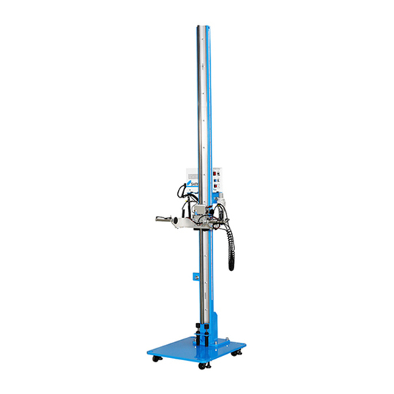
§2 Outer View §2 Outer View 221 379 104 30 540 30 600 Column Scale Guide rail Pen cylinder Control unit CONTROLLER DT-202 POWER TOTAL 123456 SET RESET DROP YOSHIDA SEIKI Drop height setting pointer Sensor Chuck Shockabsober Base Fig. 1... -
Page 11: Preparation
§3 Preparation §3 Preparation Preparation to be executed first after installation When this tester is used for the first time after mounting (or relocating) it, perform the following preliminary operation and confirm its operation according to the following procedure. Power supply A single-phase 220VAC power supply is necessary as the control power supply for this tester. -
Page 12: Preparation For Test
§3 Preparation Preparation for test Shape and size of specimens The maximum weight and the maximum size in case of face drop of a specimen should be within the rated ranges. (See §8. Performance and specifications) Check of each section Check each section (the pneumatic pen cylinders for fixing a specimen, in particular) for normal condition before starting the test. -
Page 13: Structure Of Components
§4 Structure of components §4 Structure of components Base The base is made of flat steel to enable a specimen to touch the base horizontally. Its main column is mounted on the upper face and its lifter and control unit are mounted. The base is perforated at its corners so that it can be fixed to the floor by grip anchoring (or anchor bolts). -
Page 14: Pneumatic Regulator
§4 Structure of components Pneumatic regulator Filter regulator for pneumatic pen cylinders This filter regulator is mounted on the lower side of the control unit to regulate the operating pressure of the pneumatic cylinders for fixing and releasing a specimen. Please set it over 0.49MPa at least. -
Page 15: Operation Method
§5 Operation method §5 Operation method Control unit The control unit panel is provided with [POWER], [DROP], [SET], [RESET] push-button switches, [500mm] selector switch, and [TOTAL] (total counter). A sequence control is mounted inside. The drop operation of the tester is controlled by these component parts. The push-button switches on the operation panel function as follows. - Page 16 §5 Operation method 188 Fig. 6 Control unit...
- Page 17 §5 Operation method [500mm] selector switch By selecting this switch, two dropping (specimen releasing) methods are selectable. a) [DH>500mm] A specimen drops together with the specimen supporting base and the pneumatic pen cylinders operate at the specified position to release the specimen. b) [DH<500mm] The specimen supporting base keeps stopping at the position and the pneumatic pen cylinders operate to release the specimen.
-
Page 18: Troubleshooting
§6 Troubleshooting §6 Troubleshooting [POWER] indicator lamp does not light Check the primary power supply. Check if the metal connector Co1 on the rear panel of the control unit is connected. (See 9-1 Wiring diagram) Check the power plug socket and power cord for their connection and breakage Check if the fuse mounted on the rear panel of the control unit is not blown out. -
Page 19: Daily Check
§7 Daily check §7 Daily check Lubricate the guide rail with a lubricant (recommendable product,oiltype:ISO VG10) may cause dust to be attached easily more or less. Wipe off the guide rail by a clean cloth without fail after use. The operation may change due to dust, etc. after a long time use. Check the conditions of each component (pneumatic pen cylinder operation, in particular) once every 500 times drop test. -
Page 20: Performance And Specifications
§8 Performance and specifications §8 Performance and specifications Type Drop tester Model DT-202 Specified performance Maximum specimen size 150mm in width Maximum weight of specimen Drop height range 250 ~ 2200mm Drop height setting Setting by scale and setting pointer... - Page 21 §8 Performance and specifications Attachments Single-ended wrench (8mm across flats) 1 pc. Test data 1 copy Operation manual 1 copy 100 Fig. 7 Maximum specimen size...
-
Page 22: Diagram
§9 Diagram §9 Diagram Wiring diagram 24V GND GND OPTION (Remote box use) CP C04 RB SET CP(003) S6 24V 24V 24V 1 C1 24V S5 RESET CP(004) 2 000 S7 GND CP(002) 0V DROP 3 001 S8 GND CO4(3) C S2 DROP... -
Page 23: Parts List In Wiring Diagram
§9 Diagram Parts list in wiring diagram Parts list in wiring diagram Symbol Name Model Maker Remarks Controller Plug-in type Fuse P450H (2 spare attached) Daito Tsushin Fuse holder P4-1S Plug-in type Power supply S8VM03024C OMRON Basic sequencer unit KV-10DR Keyence 6 input, 4output Total counter... -
Page 24: Pneumatic Piping Diagram
§9 Diagram Pneumatic piping diagram...
Need help?
Do you have a question about the DT-202 and is the answer not in the manual?
Questions and answers