Table of Contents
Advertisement
Quick Links
Advertisement
Table of Contents

Related Manuals for MicroRidge MICRO-RM2.4

Summary of Contents for MicroRidge MICRO-RM2.4
- Page 2 MicroRidge 2.4 GHz Radio Module Copyright © 2014-2018 MicroRidge Systems, Inc. All rights reserved. No parts of this work may be reproduced in any form or by any means - graphic, electronic, or mechanical, including photocopying, recording, taping, or information storage and retrieval systems - without the written permission of the publisher.
-
Page 3: Table Of Contents
........................... Chapter 6 Wireless Library ........................... Chapter 7 Application Board Design ........................... Chapter 8 Ordering Information ........................... Chapter 9 Radio Certification ........................... Chapter 10 Contact MicroRidge ........................... Chapter 11 Revision History ........................... Version 1.3.9 Copyright © 2014-2018 MicroRidge Systems, Inc. -
Page 4: Chapter 1 Introduction
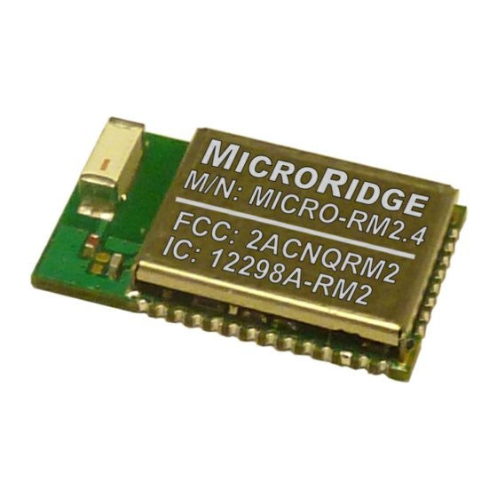
MICRO-RM2.4 follows the approved certifications. The small size of the MICRO-RM2.4 module allows it to be used in small and compact products. The module measures 12 x 20.75 x 3 mm (.472 x .817 x .118 inches). The module requires a power supply of 1.8 to 3.6 volts DC. - Page 5 MicroRidge 2.4 GHz Radio Module Introduction Basic Block Diagram A basic block diagram of the MICRO-RM2.4 Radio Module is shown below. Refer to the Atmel ATmega644/1284/2564RFR2 documentation for block diagrams with greater detail. Version 1.3.9 Copyright © 2014-2018 MicroRidge Systems, Inc.
-
Page 6: Chapter 2 Features
MicroRidge 2.4 GHz Radio Module Features Features The features of the MICRO-RM2.4 Radio Module are numerous and allow the module to be used in many low powered short range applications. The primary features of this module are as follows: §... -
Page 7: Chapter 3 Related Documents
§ The MicroRidge MICRO-RM2.4 Wireless Communication Library (RM2.4 Library) is available to assist in the development of firmware for the MICRO-RM2.4 Radio Module. In order to use the RM2.4 Library, you must purchase Radio Modules that have the library support enabled. This library is only supported on specific versions of the... -
Page 8: Chapter 4 Specifications
Atmel document. Dimensions The dimensions for the MICRO-RM2.4 Radio Module, pad locations and bottom side ground pads are presented in this section. - Page 9 MicroRidge 2.4 GHz Radio Module Specifications Transmitter characteristics Current Consumptions Specifications Version 1.3.9 Copyright © 2014-2018 MicroRidge Systems, Inc.
-
Page 10: Dimensions
Dimensions Board Dimensions The dimensions for the MICRO-RM2.4 Radio Module are given below. All of the dimensions are in mm. The thickness of the module from the bottom of the module to the top of the RF shield is 3 mm. The pad spacing is 1 mm and the pad width is 0.7 mm. - Page 11 The recommended placement of the solder pads on the application board is shown below. The 2 large pads are ground pads and they are discussed in the Ground Pads section on the next page. All dimensions are in mm. Version 1.3.9 Copyright © 2014-2018 MicroRidge Systems, Inc.
- Page 12 The size and location of the ground pads are shown in the following table. Size Distance from Upper Left Corner Ground Width, mm Height, mm Horizontal, mm Vertical, mm 3.25 2.50 6.50 5.50 2.625 5.00 14.75 2.50 Version 1.3.9 Copyright © 2014-2018 MicroRidge Systems, Inc.
-
Page 13: Solder Paste Mask
A and B. All dimensions are in mm. Gap Around Pads Number Ground of Solder Size of Solder Size Mask Pad Pads Outside Inside Coverage 1.9 x 2.5 x 3.25 52.6% 1.125 1.2 x 5 x 2.625 55.5% 2.025 Version 1.3.9 Copyright © 2014-2018 MicroRidge Systems, Inc. -
Page 14: Pin Configuration
MicroRidge 2.4 GHz Radio Module Specifications Pin Configuration The pin connections for the MICRO-RM2.4 Radio Module are show below. For a complete description of each pin refer to the Atmel ATmega644/1284/2564RFR2 documentation. MICRO-RM2.4 Pin Connections Module Description Name Ground (connected to AVSS_RFP, AVSS_RFN, DVSS & AVSS) RESET Reset input (active low). - Page 15 Port PE7 (alternate functions ICP3, INT7 & CLK) 1.8 to 3.6 VDC (connected to DEVDD & EVDD) Port PF2 (alternate function ADC2) Port PF1 (alternate function ADC1) Port PF0 (alternate function ADC0) Version 1.3.9 Copyright © 2014-2018 MicroRidge Systems, Inc.
-
Page 16: Soldering
Connected to 16 MHz crystal in the wireless module. Soldering The following J-STD-020C compliant soldering profile is recommended for the MICRO-RM2.4 Radio Module. Since the FCC and IC IDs are etched into the RF shield, there is no concern about heat from the soldering process damaging a label that contains this ID information. -
Page 17: Chapter 5 Serial Number
Parallel and JTAG interface. Each User Signature page contains 256 bytes for a total of 768 bytes The MICRO-RM2.4 Radio Module uses page 1 of the User Signature pages to store information about the Radio Module. The information on page 1 is written by MicroRidge during module testing &... -
Page 18: Chapter 6 Wireless Library
AVR microcontroller. Only the current version of the IAR compiler is supported for the RM2.4 Library. The RM2.4 Library for the MICRO-RM2.4 Radio Module will be released in the 3rd quarter of 2015. These library files will be available at www.MicroRidge-RM.com. -
Page 19: Application Board Design
A common rule of thumb is to make the via spacing less than λ/20 at the maximum operating frequency. For the MICRO-RM2.4 Radio Module, the wavelength at 2.4 GHz is 125 mm and the maximum via spacing would be 6.25 mm. - Page 20 Low profile enclosures might affect antenna performance. § Avoid placing high profile components next to antenna. § Radio module should not be placed next to other electronics which might interfere with the 2.4 GHz frequency band. Version 1.3.9 Copyright © 2014-2018 MicroRidge Systems, Inc.
-
Page 21: Chapter 8 Ordering Information
Description MICRO-RM2.4-L-TU Radio Module with RM2.4 Library support in tubes of 23 modules. MICRO-RM2.4-N-TU Radio Module with no wireless library support in tubes of 23 modules. MICRO-RM2.4-L-SG Radio Module with RM2.4 Library support. This item can only be ordered in quantities of 22 or less. -
Page 22: Chapter 9 Radio Certification
Contains FCC ID: 2ACNQRM2 The MICRO-RN2.4 Radio Module has a Modular approval and does not need separate approval for this module when used on an application board. Version 1.3.9 Copyright © 2014-2018 MicroRidge Systems, Inc. - Page 23 The MICRO-RN2.4 Radio Module has a Modular approval and does not need separate approval for this module when used on an application board. European Union (ETSI) The MICRO-RM2.4 radio module has been certified for use in European countries. The following testing has been completed. Test standard ETSI EN 300 328 V1.7.1 (2006-10): §...
- Page 24 The CE marking must be affixed visibly, legibly, and indelibly. More detailed information about CE marking requirements you can find at "DIRECTIVE 1999/5/EC OF THE EUROPEAN PARLIAMENT AND OF THE COUNCIL" on 9 March 1999 at section 12. Version 1.3.9 Copyright © 2014-2018 MicroRidge Systems, Inc.
-
Page 25: Chapter 10 Contact Microridge
Sunriver, OR 97707 Note: There is no mail delivery to this address. This address should only be used for package delivery services such as UPS, FedEx, etc. MicroRidge Web: www.MicroRidge.com MICRO-RM2.4 Web: www.MicroRidge-RM.com Version 1.3.9 Copyright © 2014-2018 MicroRidge Systems, Inc. -
Page 26: Chapter 11 Revision History
MicroRidge 2.4 GHz Radio Module Revision History Revision History Date Version Comments § 9-3-2014 1.0.1 Preliminary release of MICRO-RM2.4 User Manual § 9-12-2014 1.1.2 Minor revisions to preliminary manual. § 10-30-2014 1.2.3 Changed radio module images to reflect final FCC & IC certification numbers.
Need help?
Do you have a question about the MICRO-RM2.4 and is the answer not in the manual?
Questions and answers