Table of Contents
Advertisement
Quick Links
ACCELAIR 2 BLOWN FIBER MACHINE
P/N 89500
OPERATION AND MAINTENANCE MANUAL
Copyright 2021 by General Machine Products (KT), LLC
All rights reserved. No part of this publication may be copied,
reproduced or transmitted in any form whatsoever without the
written permission of General Machine Products (KT), LLC
GMP • 3111 Old Lincoln Hwy • Trevose, PA 19053 • USA
TEL: +1-215-357-5500 • www.gmptools.com
February 15, 2021 USA ver 04H
Manual P/N 34061
Advertisement
Table of Contents

Subscribe to Our Youtube Channel
Related Manuals for GMP ACCELAIR 2


Summary of Contents for GMP ACCELAIR 2
- Page 1 All rights reserved. No part of this publication may be copied, reproduced or transmitted in any form whatsoever without the written permission of General Machine Products (KT), LLC GMP • 3111 Old Lincoln Hwy • Trevose, PA 19053 • USA TEL: +1-215-357-5500 • www.gmptools.com February 15, 2021 USA ver 04H...
- Page 2 REVISION HISTORY Date Details Author 05/30/14 Original Issue C. Swallow 05/01/15 US Version A. Konschak 05/25/16 Added Spares A. Konschak Revised Program (multi language) 02/10/17 A. Konschak Changed menu options Updated troubleshooting guide 03/01/17 A. Konschak Updated Spares and Configuration 03/22/17 A.
-
Page 3: Table Of Contents
12. CHECKING THE ODOMETER..31 13. DETERMINING MAXIMUM TORQUE SETTING..32 14. PROCEDURE FOR CHANGING DISPLAY LANGUAGE…..33 15. TROUBLESHOOTING GUIDE..34 16. MONTHLY SERVICE – CHECK LIST..35 17. CHANGEABLE PARTS AND ACCESSORIES ..36 18. SPARES…….38 GMP Limited Warranty can be found at http:// www.gmptools.com/warranty/... -
Page 4: Safety Instructions
1. SAFETY INSTRUCTIONS THIS EQUIPMENT SHOULD BE USED ONLY BY PERSONNEL WHO HAVE BEEN GIVEN THE APPROPRIATE TRAINING AND WHO ARE COMPETENT TO USE IT. THESE INSTRUCTIONS ARE TO BE MADE AVAILABLE TO OPERA- TORS OF THIS EQUIPMENT AT ALL TIMES, FAILURE TO OBSERVE THESE SAFETY INSTRUCTIONS COULD RESULT IN SERIOUS PER- SONAL INJURY AND/OR PROPERTY DAMAGE. - Page 5 • When operating machine always wear appropriate safety clothing, ear and eye protection, hard hat, safety shoes and leather gloves. The machine operates with compressed air at up to 220 PSI (15 Bar). • Prior to installation ensure the tube route is connected properly.
- Page 6 CONNECTIONS MEET THE ELECTRICAL REGULATIONS FOR THE RELEVANT COUNTRY. The Accelair 2 machine itself runs off a 24V supply connected via a Binder Series 430 Socket. Should the connecting plug need re- placement the Red wire is positive (+ve) (Pin 1) and the Black...
- Page 7 GENERAL PNEUMATIC SAFETY INSTRUCTIONS The GMP Accelair 2 Blown Fiber Blowing Machine is a pneu- matic device, using pressurized air to project fiber at high ve- locities. Please observe the following precautions when oper- ating the Blowing Machine:- • Compressed air can cause flying debris. This could cause personal injury.
-
Page 8: Critical Points That Dramatically Affect The Operation Of The Blown Fiber Blowing Machine
• The compressed air moisture content needs to be carefully controlled, it should be dry enough to prevent moisture forming in the tubes yet not so dry to cause a static build up – GMP Products recommend the use of an air dryer with a bypass. - Page 9 DISCLAIMER GMP takes care in the design of its products to ensure that the cable is protected during installation. Due to the variety and different methods of fiber manufacture the responsibility of checking the fiber compatibility with the equipment lies with the operator.
-
Page 10: General Description
3. GENERAL DESCRIPTION The Accelair 2 Fiber Blowing Machine has been developed to provide a simple to use and reliable fiber blowing solution. The unit is designed to fit a fiber range up to 3mm diameter, thereby providing the complete range of blown fiber installation solu- tions from one machine. -
Page 11: Specification
4. SPECIFICATION Fiber Up to .8mm with buckle, up to 3mm with- Compatibility: out buckle detection Blowing Speed: Manual control up to: 0-328 ft./min (0-100m/min) without buckle detection 0-165 ft./min (0-50m/min) with buckle detection Compatible Tubes: 3mm to 10mm Automation: In buckle mode machine is self-regulating Air Supply: 15 Bar max working pressure complete with... -
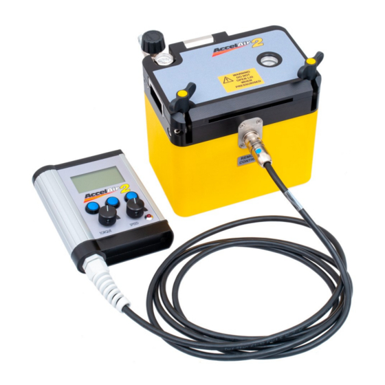
Page 12: Major Elements
5. MAJOR ELEMENTS Buckle Plates Pressure Gauge Tube Clamp Sight Glass Buckle Shuttle Wheel Opening Handle Infeed Guide Remote Connection Drive Wheels Lid Locking Screws LCD Display User Interface Buckle Indicator... - Page 13 Lid Locking Screws Air Control Valve Air Connection 24V Connection Tools/Accessories Power Wires Universal AC- Accelair 2 Remote Unit Power Supply Included with the Accelair is a removable shoulder strap for added mobility when working in multiple locations.
-
Page 14: Operating Procedure
• ARE COMPETENT TO USE IT • AUTHORIZED TO USE IT • HAVE READ AND UNDERSTOOD THIS MANUAL GMP CANNOT BE HELD RESPONSIBLE FOR MISUSE OF THIS EQUIPMENT. SETTING UP THE TUBE AND FIBER To begin an installation first we must connect the tube and fit the fiber through the machine. - Page 15 8. PROCEDURE FOR CHANGING THE BLOWING PLATES The Accelair 2 uses two types of blowing plates. One type is for use in conjunction with the buckle functionality and one with- out. The buckle plates use (4) M3 cap screws each to retain them into the machine;...
- Page 16 Place the tube seal over the end of the tube and insert into the machine as shown with the tube flush up to the air inlet and the seal in the groove. Do not allow the tube to protrude into the air inlet as this will restrict air flow and performance.
- Page 17 NEVER OPEN THE LID OF THE MACHINE WHEN IT IS UNDER PRES- SURE, SERIOUS INJURY MAY OCCUR DUE TO ITEMS EXPELLED AT HIGH VELOCITY. GMP recommends the use of a stop end at the end of the tube route to arrest the fiber at the end of the installation.
- Page 18 FIBER INSTALLATION Insure that the remote control and the power supply is connect- ed to the unit before plugging into the power source. After sup- plying power, the LCD panel on the remote unit should power up with the following display. Select the option by pressing the relevant blue button under either YES or NO depending on...
- Page 19 The two dials control the torque setting and speed. Adjustment of the torque setting is only relevant when installing fiber with the buckle functionality disabled. The torque should be set to a minimum value of 20% when buckle functionality is enabled to ensure proper operation.
- Page 20 Should the incorrect buckle mode be selected at power up select ‘MENU’ if not already there and then select ‘SETTINGS’. When on the buckle sensor option press ‘Change’ to alter this function. You can then return to the menu and resume active job;...
- Page 21 As the fiber is moved into the machine the screen will first display 'warning' and then when more fiber is fed through it will display 'active'. Eventually it will display 'error'; do not worry, this simply means the buckle shuttle has moved beyond the sensing range. In 'error' mode the machine reacts as though it were in 'active' mode.
- Page 22 The speed and torque settings can be adjusted at any time by moving the dials either clock- wise or counter-clockwise. The machine will slow instantly but will accelerate slowly as previously described After 100 - 150 feet of fiber has been installed it will be neces- sary, as resistance increases, to introduce airflow down the...
- Page 23 The installation of fiber should now be semi-automatic. If the buckle function is not in use then the machine will come to a stop when there is a blockage; the fiber will be undamaged as there will not be enough torque to break it. Once the machine has come to a stop, press ‘stop’...
- Page 24 It is advisable to finish the current job to ensure the next installation begins with the distance reset to zero. To do this select ‘OPTIONS’ from the installation screen fol- lowed by ‘Finish Job’. You will be asked to confirm this selection. Reverse Mode You are able to reverse the motor in order to pull fiber out of the duct .
-
Page 25: Maintenance
Imperial Units The Accelair 2 machine can display metric or imperial measurement formats as well as European and American date formats. To set your machine to the desired units navigate to the settings screen. Scroll down to Measurement Units and press... -
Page 26: Procedure For Changing The Blowing Plates
7. MAINTENANCE The GMP Blown Fiber Blowing Machine has been designed to give reliable, trouble free service over long periods. The machine requires no sophisticated maintenance procedures; simple com- mon sense checks and precautions are all that are needed. The main source of breakdown and/or malfunction of a machine... - Page 27 Store the removed plates in the bag provided and in the desig- nated area of the carry case to avoid loss or damage. The above figure shows the air seal beneath the lower blowing plate. This seal should sit above the surface; if it has become flattened or damaged replace to maintain a good air seal and blowing performance.
-
Page 28: Procedure For Replacing Tube Clamp Inserts And Infeed Guides
AND INFEED GUIDES Various tube clamp inserts and infeed guides are available for the Accelair 2 to allow the use of different tube and fiber sizes. Tube clamp inserts are retained using (2) M3 cap screws each and re- quire the use of the 2.5mm Allen wrench; infeed guides are re- tained using (2) M3 cap screws and require the use of the 2.5mm... -
Page 29: Procedure For Replacing Drive Wheels
10. PROCEDURE FOR REPLACING DRIVE TIRES The Accelair 2 uses replaceable silicone drive tires to provide grip to install the blown fiber. Two different sizes are available for small and large fiber. When installing a different fiber or through wear it will be necessary to replace these drive tires. -
Page 30: Procedure For Replacing Air Seals
11. PROCEDURE FOR REPLACING AIR SEALS All seals fitted to the Accelair 2 are 2 mm cord seal. When replac- ing the seal on a blowing plate it is recommended that the plate is removed from the machine. • Remove the existing seal. -
Page 31: Checking The Odometer
12. CHECKING THE ODOMETER The Accelair 2 has an odometer to indicate the total distance the machine has installed during its service life. This can be accessed via the ‘System Information’ page from the main menu. Also displayed will be the ID numbers for the Accelair 2 machine and the remote unit. -
Page 32: Determining Maximum Torque Setting
13. DETERMINING MAXIMUM TORQUE SETTING When preforming an installation of a larger or stiffer fiber it may be necessary to use a straight set of blowing plates. To ensure the integrity of the fiber at all times during the installation it is crucial a test is performed. -
Page 33: Procedure For Changing Display Language
14. CHANGING THE DISPLAY LANGUAGE The Accelair 2 machine can display in several languages – English, French, German, Spanish, Portuguese and Italian. To set your machine to the desired language navigate to the settings screen. Scroll down to ‘Language’ and press ‘SELECT’ and scroll through to se- lect the desired language. -
Page 34: Troubleshooting Guide
15. TROUBLESHOOTING GUIDE • Air loss from the Accelair 2 machine is greater than normal: • Ensure the correct plates are fitted for the fiber and tube being used. • Check air seal beneath the lower blowing plate; re- place if necessary. -
Page 35: Monthly Service - Check List
• Ensure a buckle leaf is fitted in the buckle plates and that it moves freely in the groove. • No drive/Drive wheels slipping: • Smaller drive wheels may be needed for improved grip – follow section 10 for details on changing drive wheels. -
Page 36: Changeable Parts And Accessories
17. CHANGEABLE PARTS AND ACCESSORIES Stainless Fiber Buckle Plates includes 5 Buckle Shuttles Description 89440 1.0mm 89441 1.2mm 89442 1.4mm 89443 1.5mm Stainless Fiber Blowing Plates Description Fiber Buckle Plates Stainless 89661 2.0mm 89662 2.1mm 89667 2.5mm 89671 3.0mm Infeed Guides Description 89478 .08 - 2.0mm... - Page 37 89703 Other sizes of clear tube connector are available. Air flow meter can be used to check route integrity. Please contact the GMP sales office to order or enquire about parts not listed; always quoting the machine type and serial number.
-
Page 38: Spares
18. SPARES 89436 Spare Buckle Shuttles 5/pk 89437 - Lower Plate Seals 5/pk Version 1 Power Supply 89501 89435 89583 Note: Version 1 and 2 power supplies are not interchangeable Version 2 Power Supply 34047 - Input Air Hose 89522 89524 Replacement Remote Control 34828... - Page 39 18. SPARES (continued) 34796 33814 Nylon Retaining Wing Screw Washer Version 2 33502 Wing Screw Version 1 32962 33035 33039 Adapter Needle Valve Plug 89691 2mm Cord Seal 3 ft. 34709 Pressure Gauge...
- Page 40 GMP • 3111 Old Lincoln Hwy • Trevose, PA 19053 • USA TEL: +1-215-357-5500 • www.gmptools.com...
Need help?
Do you have a question about the ACCELAIR 2 and is the answer not in the manual?
Questions and answers