Table of Contents
Advertisement
Quick Links
All rights reserved. No part of this publication may be copied, reproduced or transmitted in any form whatso-
ever without the written permission of General Machine Products (KT), LLC
General Machine Products (KT), LLC • 3111 Old Lincoln Hwy • Trevose, PA 19053 • USA
TEL: +1-215-357-5500 • FAX: +1-215-357-6216 • WEB: www.gmptools.com
Operation and Maintenance
Model 89300
CABLE BLOWING MACHINE
Page 1 of 41
Manual P/N 36287 Ver 6a
071717 AKK
Advertisement
Table of Contents

Subscribe to Our Youtube Channel
Related Manuals for GMP Air Stream 89300


Summary of Contents for GMP Air Stream 89300
- Page 1 CABLE BLOWING MACHINE Operation and Maintenance Model 89300 All rights reserved. No part of this publication may be copied, reproduced or transmitted in any form whatso- ever without the written permission of General Machine Products (KT), LLC General Machine Products (KT), LLC • 3111 Old Lincoln Hwy • Trevose, PA 19053 • USA TEL: +1-215-357-5500 •...
- Page 2 REVISION HISTORY: Rev.no Date Details Author Jul -27-10 Original issue A. Sibun Feb-1-11 Reformat for US A. Konschak May -19-11 Updated photos to newer design A. Konschak Nov-20-12 Update to reflect new design without remote A. Konschak Update grounding and belt replacement info April-09-13 A.
-
Page 3: Table Of Contents
17. Tube integrity and Lubrication 18. Recommended Spares List APPENDICES Appendix 1 Cable and tube insert selection chart. Appendix 2 Recommended torque control potentiometer settings Appendix 3 Counter/Ratemeter Programming Instructions GMP Limited Warranty can be found at http://www.gmptools.com/warranty/ Page 3 of 41... -
Page 4: Safety Instructions
1.0 SAFETY INSTRUCTIONS THIS EQUIPMENT SHOULD BE USED ONLY BY PERSONNEL WHO HAVE BEEN GIVEN THE APPROPRIATE TRAINING, AND WHO ARE COMPETENT TO USE IT. THESE INSTRUCTIONS ARE TO BE MADE AVAILABLE TO OPERATORS OF THIS EQUIPMENT AT ALL TIMES, FAILURE TO OBSERVE THESE SAFETY INSTRUCTIONS COULD RESULT IN SERIOUS PERSONAL INJURY AND/OR PROPERTY DAMAGE. - Page 5 been installed into the tube. 23. Ensure the cable drum rotates freely on its stand, the cable should leave from the top of the drum. 24. The cable should enter the machine in a clean and dry condition. In damp, dusty atmospheres, the cable should be cleaned continuously as it enters the machine.
- Page 6 GENERAL PNEUMATIC SAFETY INSTRUCTIONS The GMP Fiber Optic Cable Blowing Machine is a pneumatic device, using pressurized air to project cable at high velocities. Please observe the following precautions when operating the Cable Blowing Machine: ► Compressed air can cause flying debris. This could cause personal injury. Always wear personal protective equipment.
-
Page 7: Critical Points
2.0 CRITICAL POINTS THAT DRAMATICALLY AFFECT THE OPERATION OF THE CABLE BLOWING MACHINE PRESSURE ON THE CABLE (POSITION OF THE CLOSE ARM ASSY) SHOULD BE SET AS ► PER THE INSTRUCTIONS BELTS TO BE CLOSED AT ALL TIMES WHEN CABLE IS INSTALLED INTO MACHINE. ►... - Page 8 DISCLAIMER General Machine Products (KT), LLC takes care in the design of its products to insure that the cable is protected during installation. Due to the variety and different methods of cable manufacture the responsibility of checking the cable compatibility with the equipment lies with the operator. Therefore, General Machine Products cannot accept liability for any damage to the cable.
-
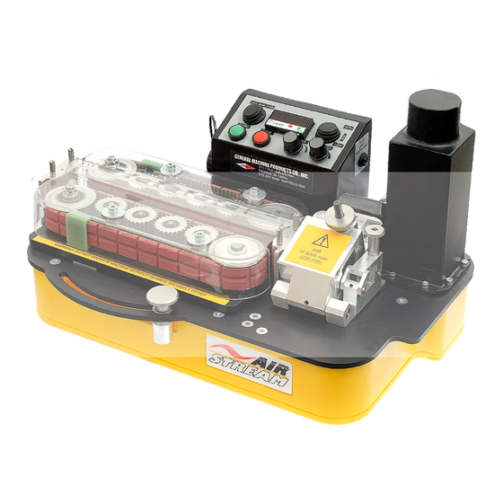
Page 9: General Description
GENERAL DESCRIPTION The GMP AirStream machine is designed to install small diameter cable into underground tubes. The machine uses a DC servo motor and reduction gearing to drive a pair of flexible belts (both belts are driven). The belts are covered with a soft pliable coating to prevent damage to the cable. The belts offer a large surface area in contact with the cable ensuring high grip with reduced compressive loading. -
Page 10: Specification
4.0 SPECIFICATION Cable size: 2.5 to 11.0 mm 0.118" to 0.433" Tube size: (OD) 5 to 18.0 mm 0.197" to 0.708" Cable speed: 0-80 m/min. 0-262 ft/min Maximum pushing force: 20 Kg. 44 lb. Maximum air pressure: 15 bar. 210 psi. 100-277Vac 50/60 Hz Power requirements:* (power supply input) -
Page 11: Operating Procedures
5.0 OPERATING PROCEDURE IT IS IMPERATIVE THAT ALL PERSONS USING, OPERATING OR MAINTAINING THIS CABLE BLOWING MACHINE: ▪ HAVE RECEIVED COMPREHENSIVE TRAINING IN THE USE OF THIS MACHINE. ▪ ARE COMPETENT TO USE IT, ▪ AUTHORIZED TO USE IT AND ▪... - Page 12 Fit the tube into which the cable is to be installed into the air box and tube clamp. It is recommended that a length of tube similar in size to the tube into which the cable is to be installed be fitted in the tube clamp.
- Page 13 Fit the cable through the machine. Loosen the thumb nut and open the seal housing Move the close assembly to the far right to fully open the drive belts It is now possible to insert the cable in the machine, this can be carried out in 2 ways.
- Page 14 Method 2: • Open the close assembly arm fully to the right. • Remove the top halves of the belt infeed and exit guides using the knurled screws (screwdriver slots are provided if necessary). Ensure the correct guides are fitted for the cable (see appendix 1) •...
- Page 15 Connect the air supply to the machine. The air inlet to the machine is male via a crowfoot coupling on the back of the airbox. An on/off valve is fitted to the air box to provide control of the air supply to the operator and a pressure gauge is fitted to the air box to indicate air box pressure.
- Page 16 This machine operates in conjunction with the machine sited at the main point of installation. The GMP Airstream machine is ideally suited to this type of operation, it may be coupled with a second machine to increase the distance a single cable can be installed without joins.
- Page 17 ‘Green’ button once shows what is being displayed – Speed or distance. Tacho represents speed, Count represents distance while displaying the distance only it is possible to reset by pressing the left hand ‘Red’ button. Should it be necessary to replace the speed distance – measuring device please contact GMP Products.
- Page 18 DOWN for low torque. Note: It is not possible to switch between high and low torque once the belts are moving. To switch the torque press STOP, change the torque switch setting and start again. Forward/Reverse Switch: This will change the direction of the belts but only when the machine is stationary to prevent accidental reversing of the machine while installing cable.
- Page 19 Grounding the Airstream Cable Blower. Certain cable/duct combinations can generate large static build-ups, this can cause the Airstream to reset and stop without apparent reason and in severe cases damage the machine. If this is occurring, ground the Airstream via the ground point on the air box via a suitable copper conductor to a ground at the power source or earth.
-
Page 20: Maintenance
6.0 Maintenance The GMP AirStream Cable Blowing Machine has been designed to give reliable, trouble free service over long periods. The machine requires no sophisticated maintenance procedures, simple common sense checks and precautions are all that are needed. The main source of breakdown and/or malfunction of a machine being used outdoors is contamination by the elements, this contamination may be introduced into the machine in a number of different ways. -
Page 21: Procedure For Changing Inserts In The Tube Clamp
7.0 Procedure for changing inserts in the tube clamp ► Loosen the thumb nut, rotate the swing bolt to open the tube clamp hous- ► Loosen and remove the (2) m2.5 fixing screws. (Do not lose these screws, they will be needed for the replacement in- sert). -
Page 22: Procedure For Changing Inserts In The Infeed And Exit Guides
9.0 Procedure for changing inserts in the belt infeed and exit guides Long Insert Unscrew knurled screws securing the upper guide housing If both long and short inserts are used, the long inserts are mounted in the housings at the machine inlet Loosen and remove the M2.5 screw securing the guide into the housing Remove and replace the guide... -
Page 23: Procedure For Replacing The Air Box Housing Seal
10.0 Procedure for replacing the air box housing seal Spread adhesive along one side of cord. Apply a thin coat of 3M Rubber Cut a length of 0.08inch seal- and Gasket Adhesive to the top of ing material 2 1/8” long (a little the cut sealing material longer than is necessary). -
Page 24: Procedure For Changing The Air Box Infeed Guide
11.0 Procedure for changing the air box infeed guide ► Loosen and remove the (2) M3 screws. (Do not mislay these screws, they will be needed for the new infeed guide. ► Remove the air box infeed guide ► Repeat the procedure for the infeed guide insert in the other hos- ing half ►... - Page 25 loosen the tension screws remove the belt guides loosen and remove the tension nuts remove the idler pulleys and the belts Place the new belt in position on the drive pulley, loop the belt on the idler pulley on the other end and place the it onto the tensioning shaft.
-
Page 26: Procedure For Tensioning The Drive Belts
13.0 Procedure for tensioning the drive belts Place the new belt in position in over the pulleys and ensure the belt is correctly located in all the pulley grooves. Tighten the tension screw with the tension nut slackened off slightly. This will begin to tighten the belt. -
Page 27: Procedure For Checking And Replacing The Motor Drive Belt
14.0 Procedure for checking and replacing the motor drive belt Remove the 6 screws retaining the machine base as shown below: Turn the machine over revealing the motor drive belt. Loosen the set screw retaining the idler pulley, as indicated below. The shaft retaining the pulley should now be free to remove, Once removed the belt can easily be replaced. -
Page 28: Monthly Service - Check List
15.0 Monthly service – check list This section is included in the manual for your convenience, there follows a list of suggested checks, it is recommended that these checks be carried out on a regular basis, depending on use. Monthly checks are convenient;... -
Page 29: Service History Record
16.0 SERVICE HISTORY RECORD Carried out Service no Date Record of service/repair Page 29 of 41... -
Page 30: Tube Integrity And Lubrication
17.0 Tube integrity and Lubrication This is entirely the responsibility of the operator. To be sure that the tube into which the cable is to be inserted is installed appropriately, it is recommended that its integrity and lubrication be checked. i.e. - Page 31 The air box and tube clamp are now set up to blow air through the tube. Connect the air as for normal blowing. Make sure there are personnel at the other end of the tube run, and that they are aware that the air is to be turned on.
-
Page 32: Recommended Spares List
18.0 Recommended spares list 1. Tube –‘O’ Rings – See Appendix 1 2. Cable Seal – See Appendix 1 3. Coated Cable Drive Belts – See Appendix 1 4. 2 mm cord seal – See Appendix 1 5. 7 A Fuses - P/N 30936 6. - Page 33 APPENDIX 1 This section lists the appropriate inserts collets etc required for a given cable/tube combination. TUBE COLLET AND CLAMP ASSEMBLIES 89310 TUBE COLLET AND CLAMP ASSEMBLY 05 mm O.D. 89311 TUBE COLLET AND CLAMP ASSEMBLY 07 mm O.D. 89312 TUBE COLLET AND CLAMP ASSEMBLY 08 mm O.D.
- Page 34 APPENDIX 2 This section makes recommendations for the initial setting of the torque control potentiometer when installing a cable which has not been installed before, and, whose characteristics are unknown. The picture to the left shows the torque and speed control potentiometers set in the maximum counter-clockwise position.
- Page 35 Establish the stiffness coefficient from the table below: the stiffness coefficient is a figure used to represent the diameter and the stiffness of a cable. This figure is only relevant in the context of setting the torque, it has no other relevance. The higher the U figure the stiffer the cable. There is a degree of subjectivity about determining the cable stiffness.
- Page 36 Referring to the chart below. The “x” axis (the bottom line) represents the coefficient of friction; 1 is very low: 10 is very high. Look along this line from left to right. Pick a vertical line that is approximately the value of the coefficient of friction.
- Page 37 Note: This method may also be used to set the clamping force of the belts on the cable. Initially, the clamp arm lever should be set so that the belts press very lightly onto the cable. Carry out the test outlined above (drive the cable into the closed end of a sample tube). The belts will slip. Repeat this procedure, each time increasing slightly, the pressure the belts apply to the cable.
- Page 38 APPENDIX 3 • Press and hold both buttons. o After 5 seconds ‘ProG’ will be displayed. Releasing the buttons will display ‘no’ • Press o ‘Yes’ is displayed • Hold and press o ‘InPol’ is displayed • Press until ‘nPn’ is displayed •...
- Page 39 • Press • Enter value 01.0 • Hold and press o ‘EndPro’ is displayed • Press un l ‘YES’ is displayed • Hold and press o Programming completed OR • Press un l ‘no’ is displayed • Hold and press o Programming mode restarted Page 39 of 41...
- Page 40 BLOWING ACCESSORIES Airstream Compressor P/N 89011 The Air Compressor is designed specifically for use with our Micro Fiber Cable Blowing Machines. This reliable & efficient screw compressor, powered by a gasoline engine, provides a maximum working pressure of 220 psi (15 bar) with 35.3cfm (1000 litres/m) flow. The compressor is modified to include an after-cooler and water separa- tor.
- Page 41 GMP • 3111 Old Lincoln Hwy • Trevose, PA 19053 • USA TEL: +1-215-357-5500 • FAX: +1-215-357-6216 • WEB: www.gmptools.com Page 41 of 41...
Need help?
Do you have a question about the Air Stream 89300 and is the answer not in the manual?
Questions and answers