Table of Contents
Advertisement
Quick Links
NOTES
:
Carefully read the user manual before using, and keep it well for future
reference.
Carefully check the device parts list before using. For any doubt, contact
distributor immediately.
Due to the product upgrade, tiny difference between the user manual
and the device will not be further noticed. Take the device as standard.
NexBat NB360 12V /24V Battery Analyzer
Advertisement
Table of Contents

Subscribe to Our Youtube Channel
Related Manuals for Nexas NexBat NB360


Summary of Contents for Nexas NexBat NB360
- Page 1 NexBat NB360 12V /24V Battery Analyzer NOTES : Carefully read the user manual before using, and keep it well for future reference. Carefully check the device parts list before using. For any doubt, contact distributor immediately. Due to the product upgrade, tiny difference between the user manual...
- Page 2 NexBat NB360 12V /24V Battery Analyzer Disclaimer All information, illustrations, and specifications contained in this manual are based on the latest information available at the time of publication. The right is reserved to make change at any time without notice.
-
Page 3: Table Of Contents
NexBat NB360 12V /24V Battery Analyzer Table of Contents Chapter 1 General Information ..............3 1.1 Product Profile ................3 1.2 Product Feature ................3 1.3 Testing Range ................4 1.4 Specifications ................5 Chapter 2 Product Description ............... 6 Chapter 3 Operation ................. -
Page 4: Chapter 1 General Information
Chapter 1 General Information 1.1 Product Profile NB360 Battery Tester adopts the conductance testing technology to easily, quickly and accurately measure the actual cold cranking amps capability of the vehicle starting battery, healthy state of the battery itself, and common fault of the vehicle starting system and charging system, which can help technician to find the problem quickly and accurately. -
Page 5: Testing Range
generally conclude that the starting system is functioning properly. But, if the starter does not crank, cranks too slowly, or the volts reading is not within specifications, further testing will be required. To get more accurate results, this scan tool incorporates a temperature compensation feature to aid in tests. Before performing the STARTER TEST, the starting system should be visually inspected for physical defects, and some preliminary checks should be performed that will aid you in diagnosing a starting system problem. -
Page 6: Specifications
1.4 Specifications Screen: 2.8” TFT 262K true color, 320*240 QVGA LCD display Input voltage range: 8~36V Operating current: <100mA@12V (Typical) Power consumption: < 1.2W (Typical) Operating temperature: 32° F~122° F / 0° C~50° C Storage tempetature: -4° F~158° F / -20° C ~70° C @ RH60% ... -
Page 7: Chapter 2 Product Description
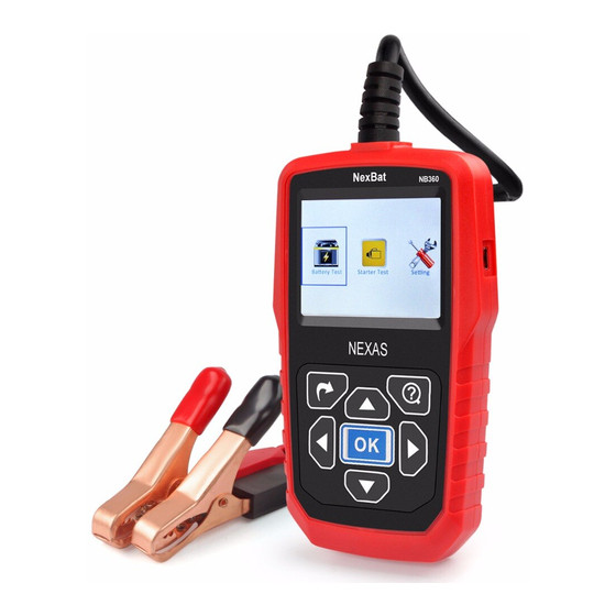
Chapter 2 Product Description Name Descriptions Connects the NB360 to the vehicle’s battery. ① Cable ② LCD display Indicates test results. ③ ESC button Confirms a selection (or action) from menu list. ⑤/⑧ button Move cursor up or down for selection. ④/⑨... -
Page 8: Chapter 3 Operation
Chapter 3 Operation 3.1 Pre-Test Before testing, clean battery poles with metal wire brush and alkaline detergent to avoid the tolerance caused by oil and dust to the test result. While testing, ensure none of the in-vehicle electrical appliance is on, doors are closed and the ignition key is in OFF status. -
Page 9: Tester Startup
3.2 Tester Startup The tester automatically starts up after the clamps are correctly connected, and displays the startup interface, within this 2 seconds, it enters the function menu. as shown in Figure 1. Figure 1 Figure 2 3.3 24V Test Ordinary 24V battery group combines two 12V batteries in series connection. -
Page 10: Battery Test
3.4 Battery Test After entering battery test program, the tester will display the tester model and version approx. 2 seconds, see figure 1. The tester will display the following contents in a sequence, select the desired items accordingly. 3.3.1 IN-VEHICLE or OUT-OF-VEHICLE Press UP/DOWN key to select the battery location, in-vehicle or out- -of-vehicle, then press OK key to confirm. -
Page 11: Select Battery Type
Now the tester detects the surface charge has been eliminated, turn lights off as prompted, then press OK key. The tester will recover automatic test. OUT OF VEHICLE means battery is not connected with any of the vehicle load, namely, battery connection is cut off. 3.3.2 Select Battery Type After the battery charge status is chosen, the tester will enter battery type selection interface: Regular Flooded, AGM Flat Plate, AGM Spiral or Gel battery. - Page 12 MCA: Marine Cranking Amps standard, effective starting current value at 0° C. JIS: Japan Industrial Standard, displayed on the battery as combination of the numbers and letters, e.g. 55D23, 80D26. DIN: German Auto Industry Committee Standard IEC: Internal Electro technical Commission Standard European Automobile Industry Association Standard SAE: Society of Automotive Engineers Standard China National Standard...
-
Page 13: Battery Test Result
Input correct test standard and rating, press OK key, It takes around 3 seconds to display the battery test result as shown below. 3.3.4 Battery Test Result Battery test result is mainly classified into 5 types: 1) Good Battery Figure 9 Figure 10 The battery is in good health, please be free to use! 2) Charge Battery... - Page 14 The battery is near to or already reached the end of its service life, replace it immediately, otherwise, potential hazard will be followed. 4) Bad Cell The battery has internal damage, broken cell or short circuit, please replace it. 5) Charge, Retest Figure 13 Unstable battery shall be recharged and retested to avoid error.
-
Page 15: Starter Test
3.5 Starter Test Tester prompts as following: Figure 14 Figure 15 NOTE: While the system prompts you to start engine, pressing RETURN key can not exit the current interface. Follow the on-screen instructions to start the engine, the tester will automatically complete the cranking test and display the result. - Page 16 Since most of the vehicle generators are using built-in regulator, the generator assembly has to be replaced. (For some old style cars using external regulator, directly replace the regulator.) The normal high volt of the voltage regulator is maximum 14.7± 0.5V.If charging volt is too high, it will overcharge the battery.
-
Page 17: Tool Setup
3.6 Tool Setup As shown on figure 17. 3.6.1 Select Language The language include English, Spanish, French, Italian, German, Russian, Finland, Portuguese, Swedish, Polish etc. Figure 18 Figure 19 3.6.2 Beep Pressing key can beep if select ON as shown in figure 19. 3.6.3 Tool Information This item show the software version, hardware version and SN. -
Page 18: Chapter 4 Daily Maintenance
Chapter 4 Daily Maintenance 4.1 Troubleshooting 4.1.1 Screen Not Light Check whether the battery is well connected or reverse connection between the positive pole and negative pole exists or not. Check whether the test cable is broken off or dropped down.
Need help?
Do you have a question about the NexBat NB360 and is the answer not in the manual?
Questions and answers