Table of Contents
Advertisement
Advertisement
Table of Contents

Subscribe to Our Youtube Channel
Related Manuals for Nexas NexLink NL101


Summary of Contents for Nexas NexLink NL101
- Page 1 NexLink NL101 User Manual NEXAS www.nexastech.com V1.2...
- Page 2 NexLink NL101 User Manual Disclaimer All information, illustrations, and specifications contained in this manual are based on the latest information available at the time of publication. The right is reserved to make change at any time without notice. Safety Precautions and Warnings To prevent personal injury or damage to vehicles and/or the NL101, please read this user’s manual first carefully and observe the following safety...
-
Page 3: Table Of Contents
NexLink NL101 User Manual TABLE of CONTENTS 1. INTRODUCTION ................... 1 2. GENERAL INFORMATION ..............1 2.1 O (OBD) II ............1 OARD IAGNOSTICS 2.2 D (DTC ) ..........2 IAGNOSTIC ROUBLE ODES 2.3 L (DLC) ......... 3 OCATION OF THE ONNECTOR 2.4 OBD II M... - Page 4 NexLink NL101 User Manual...
-
Page 5: Introduction
NexLink NL101 User Manual 1. INTRODUCTION The NL101 is specially developed for car, min van and light vehicles, which supports all 10 modes of OBDII test (EVAP, O2 Sensor, I/M Readiness, MIL Status, VIN Info, and On-board monitors testing etc.) for a complete diagnosis and enables users to read DTCs, clear DTCs and view the live engine data stream with a live color graphing. -
Page 6: Diagnostic Trouble Codes (Dtcs)
NexLink NL101 User Manual Which, if any, Diagnostic Trouble Codes (DTCs) are stored; Readiness Monitor status. 2.2 Diagnostic Trouble Codes (DTCs) Diagnostic Trouble Codes (DTC) are codes that are stored by the on-board computer diagnostic system in response to a problem found in the vehicle. -
Page 7: Location Of The Data Link Connector (Dlc)
NexLink NL101 User Manual 2.3 Location of the Data Link Connector (DLC) The DLC (Data Link Connector) is the standardized 16-cavity connector where diagnostic scan tools interface with the vehicle's on-board computer. The DLC is usually located 12 inches from the center of the instrument panel (dash), under or around the driver side for most vehicles. -
Page 8: Obd Ii Definitions
NexLink NL101 User Manual result in Readiness Monitors being set to Not Ready.Since the three continuous monitors are constantly evaluating, they will be reported as Ready all of the time. If testing of a particular supported non-continuous monitor has not been completed, the monitor status will be reported as Not Complete or Not Ready. -
Page 9: Obd Ii Modes Of Operation
NexLink NL101 User Manual the “ready” condition. The purpose of completing an OBD II drive cycle is to force the vehicle to run its onboard diagnostics. Some form of a drive cycle needs to be performed after DTCs have been erased from the PCM’s memory or after the battery has been disconnected. - Page 10 NexLink NL101 User Manual Mode $03–Displays the type of powertrain or emission related DTCs stored by a 5 digit code identifying the faults. There may be more than one response message if there are more trouble codes than will fit in the data bytes...
- Page 11 NexLink NL101 User Manual Mode $08–This special Control Mode requests control of the on-board system, test, or component bi-directionally (where applicable). This mode is manufacturer specific. Mode $09–Reports vehicle information. This information includes vehicle VIN number and calibration information stored in the vehicle ECUs.
-
Page 12: Product Descriptions
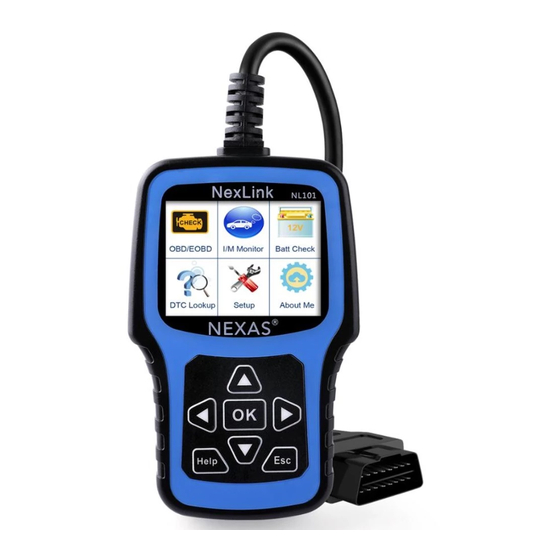
NexLink NL101 User Manual 3. Product Descriptions 3.1 Outline Figure 3-1 Name Descriptions Connects the NL101 to the vehicle’s Data ① OBD II Cable Link Connector (DLC). ② LCD display Indicates test results. ③ ESC button Returns to previous menu. -
Page 13: Specifications
NexLink NL101 User Manual ④/⑨ button Move cursor right or left for selection; Or turn page up or down when more than one page is displayed. ⑥ USB port Connects to computer to update online. ⑩ OK button Confirms a selection (or action) from menu list. -
Page 14: Battery Monitor
NexLink NL101 User Manual remove it before plugging the OBD II cable. If it cannot be found, refer to the vehicle’s service manual for the location. 2. Plug OBD II cable to the vehicle’s DLC. 3.5 Battery Check NL101 could quickly check the vehicle’s battery health, read out the current battery value and give out 6 levels of warnings for your knowledge: A, <10.8V(before Starting): Too Low;... -
Page 15: Connections & General Operations
NexLink NL101 User Manual 4. Connections & General Operations 4.1 Connections 1. Turn the ignition off. 2. Locate the vehicle’s DLC ( Vehicle Diagnostic Socket). 3. Plug the OBD 16PIN Diagnostic cable to the vehicle’s diagnostic socket; 4. Turn the ignition on. Engine can be off or at idle running. -
Page 16: Ready Test
NexLink NL101 User Manual 4.2 I/M Ready Test The Ready Test can be used as a convenient readiness test tool by automotive technicians to determine if the tested vehicle is ready for an emission test. By visual and audible indication,you will learn a vehicle’s monitors readiness. - Page 17 NexLink NL101 User Manual 2. From DTC Lookup screen,use the [ ] / [ ] button to move to the desired character,use the [ ] / [ ] button to change selected digit/character and press the [OK] button to confirm.
-
Page 18: Diagnose
NexLink NL101 User Manual 5. Diagnose When more than one vehicle control module is detected by the scan tool, you will be prompted to select the module where the data may be retrieved. The most often to be selected are the Power train Control Module [PCM] and Transmission Control Module [TCM]. -
Page 19: Read Codes
NexLink NL101 User Manual 7) View a summary of system status (MIL status, DTC counts, Monitor status) on screen. Press [ ] ,a screen similar to Figure 5-9 will appear: Figure 5-9 5.1 Read Codes This option is used to read the current, pending or permanent trouble codes. -
Page 20: Erase Codes
NexLink NL101 User Manual screen will show the detailed content of the trouble code. Some DTC have the tips guide, it is the next page of Figure 5-11.It shows the structures of sensor , the cause and Results of Fault and give you the parameters and inspection method. -
Page 21: View Freeze Frame
NexLink NL101 User Manual 5.5 View Freeze Frame When an emission-related fault occurs, certain vehicle conditions are recorded by the on-board computer. This information is referred to as freeze frame data. Freeze Data is a snapshot of the operating conditions at the time of an emission-related fault. -
Page 22: Faq
NexLink NL101 User Manual 6. FAQ Here we list some frequently asked questions and answers relating to NL101. Question: System halts when reading data stream. What is the reason? Answer: It may be caused by a slackened connector. Please turn off the NL101, firmly connect the connector, and switch on it again. - Page 23 NexLink NL101 User Manual "UPGRADE" to finish the update; 4, Please go to software menu " SETUP' ---" Tool Info" to check if it is latest software version; Note: All pictures illustrated here are for reference and demonstration purpose only and this User’s Manual is subject to change without prior notice.
- Page 24 NexLink NL101 User Manual NEXAS TECH CO.,LTD www.nexastech.com ---------------------------------------------------------------...
Need help?
Do you have a question about the NexLink NL101 and is the answer not in the manual?
Questions and answers