Table of Contents
Advertisement
Quick Links
Advertisement
Table of Contents

Related Manuals for BOREAL LASER GasFinder FCr

Summary of Contents for BOREAL LASER GasFinder FCr
- Page 1 Boreal Laser Inc. GasFinderFCr Operation Manual July 17th 2017 BOREAL LASER INC. GasFinder FCr Operation Manual GasFinderFCr Menu ver. 1.10.c Part No. NDC-200005-D 12846 146 Street NW • Edmonton, Alberta • CANADA • T5L 2H7 Phone: +1 780 488 5173 • Fax: +1 780 488 0780 • www.boreal-laser.com...
- Page 2 Boreal Laser Inc. makes no representations or warranties with respect to the contents of this document. Boreal Laser Inc. assumes no responsibility for errors or omissions or any damages resulting from the use of the information contained in this document. Information in this document is subject to change without notice.
-
Page 3: Table Of Contents
Boreal Laser Inc. GasFinderFCr Operation Manual July 17th 2017 BOREAL LASER INC. BOREAL LASER INC. GasFinderFCr O P E R A T I O N M A N U A L Contents Section 1. System Description ..................1.1 Specifi cations ....................... 1.3 GasFinderFCr ........................1.3... - Page 4 Boreal Laser Inc. GasFinderFCr Operation Manual July 17th 2017 Section 5. Operating Instructions ................... 5.1 Start Up ........................5.1 Menu Details ........................ 5.3 Main Menus ........................5.3 System Menus ......................5.6 Password Protected Menus ..................5.8 Section 6. Maintenance ....................6.1 GasFinderFCr ......................6.1 Remote Heads &...
- Page 5 • Refer all servicing to qualifi ed personnel only. The unit contains no user servicable parts. Disclaimer Boreal Laser Inc. assumes no liability or responsibility for issues or harm resulting from the use of this equipment.
- Page 6 Boreal Laser Inc. GasFinderFCr Operation Manual July 17th 2017 OP1 Remote Head 2 OP1 Remote Heads OP3 Remote Head 2 OP3 Remote Heads in stainless steel enclosures V1 Duct Probe GasFinderFCr mounted in cabinet...
- Page 7 Boreal Laser solution from meeting all customer expectations. Boreal Laser will make every reasonable effort to work with the customer to modify an installation to meet requirements for up to 12 months after installation. Should these efforts fail, Boreal Laser will negotiate with the client for the removal and return of Boreal supplied equipment.
- Page 8 GasFinderFCr Operation Manual July 17th 2017 ENHANCED WARRANTY Boreal Laser can quote Enhanced Warranty on a project specifi c basis to include some or all of the following: • Include all non Boreal Laser manufactured items supplied on a specifi c job.
-
Page 9: Section 1. System Description
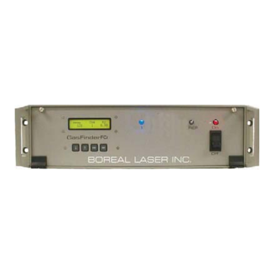
July 17th 2017 Section 1. System Description Boreal Laser’s patented (US Patent 5,637,872) TDL (Tunable Diode Laser) fi bre coupled monitor measures gas concentration over an open path. The monitoring system consists of a rack mounted integrated transmitter/receiver known as the Central Control Unit (CCU), an open path transceiver head or duct probe, and a remote, passive retrorefl... - Page 10 Boreal Laser Inc. GasFinderFCr Operation Manual — System Description July 17th 2017 The three main parts of the equipment are: • GasFinderFCr, or CCU • Open Path Transceivers or Remote Heads and Duct Probes • Remote Refl ectors, or Retros GasFinderFCr •...
-
Page 11: Specifi Cations
Boreal Laser Inc. GasFinderFCr Operation Manual — System Description July 17th 2017 Specifi cations GasFinderFCr Weight 8.5kg (18.7 lb) Dimensions (L x W x H) 374 x 446 x 132mm (14.7 x 17.6 x 5.2ins) See drawing Section 10. Power Requirements... -
Page 12: Certifi Cation
Safety Concerns Boreal Laser’s GasFinderFCr contains an invisible (infrared) laser source. The infrared laser and red aiming lasers conform to Class 1 as per IEC 60825-1 and are eye- safe. They do not require the use of protective eye wear, protective equipment, or outdoor control measures. -
Page 13: Section 2. Pre-Installation Checks
Boreal Laser Inc. GasFinderFCr Operation Manual — Pre Installation July 17th 2017 Section 2. Pre-Installation Checks GasFinderFCr A site survey should be undertaken to check the following points: • Temperature Limits: the GasFinderFCr cabinet should be located in a temperature regulated (10... -
Page 14: Equipment Check
Boreal Laser Inc. GasFinderFCr Operation Manual — Pre Installation July 17th 2017 the refl ector enclosure should be attached with the front window perpendicular to the path. There should be no obstructions in the path between the retrorefl ector and the head. -
Page 15: Section 3. Installation
(conforms to Class 1 as per IEC 60825-1) and will not damage eye tissue. However, it is the recommendation of Boreal Laser Inc. that, as with ANY LASER SYSTEM, the user/ operator should avoid staring directly into the output aperture of the instrument. - Page 16 The enclosures will vary in size depending on the number of retros and if internal heating is required. Window materials will depend on the site conditions and the gas to be measured. Lexan is normally supplied but window glass, boro-silicate and sapphire are used under specifi c circumstances. Contact Boreal Laser Inc. for more information.
-
Page 17: Condensation
Boreal Laser Inc. GasFinderFCr Operation Manual — Installation July 17th 2017 Condensation Condensation on the surface of the window is caused by the window temperature falling below the dew point. This may occur in areas of high humidity or large temperatures differences between day and night. -
Page 18: Op1 Remote Head
Boreal Laser Inc. GasFinderFCr Operation Manual — Installation July 17th 2017 Transceivers (Remote Heads, Duct Probes) There are various types of transceivers to which the GasFinderFCr can be connected: - OP1 - OP3 - V1 OP1 Transceiver (Remote Head) This Remote Head is designed to be used for path lengths up to 50m. - Page 19 Boreal Laser Inc. GasFinderFCr Operation Manual — Installation July 17th 2017 OP3 Open Path Transceiver (Remote Head) This Remote Head is designed to be used for path lengths up to 750m. It can be fi tted in an enclosure and uses an X-Y mount and scope for alignment. It can also be used mounted on a tripod for portable use.
-
Page 20: Optical Alignment
Boreal Laser Inc. GasFinderFCr Operation Manual — Installation July 17th 2017 and twisting the tabs on the inside. Nose Tabs Front of enclosure • Remove the two locking screws for the bottom plate of the XY mount and raise the top two plates.Use the two 8 x 32 x ”... - Page 21 (conforms to Class 1 as per IEC 60825-1) and will not damage eye tissue. However, it is the recommendation of Boreal Laser Inc. that, as with ANY LASER SYSTEM, the user/ operator should avoid staring directly into the output aperture of...
-
Page 22: Adjusting The Aiming Scope
Boreal Laser Inc. GasFinderFCr Operation Manual — Installation July 17th 2017 Adjusting the Aiming Scope Cross Hairs Aiming Scope If the cross hairs on the scope do not line up with the centre of the retrorefl ector, they can be adjusted by unscrewing... - Page 23 Boreal Laser Inc. GasFinderFCr Operation Manual — Installation July 17th 2017 V1 Duct Transceiver (Duct Probe) The Duct Probe is designed for use across ducts and stacks and consists of a laser emitter and receiver in one unit. The laser beam is targeted on a retrorefl...
-
Page 24: Fibreoptic
However, as with all laser instruments, it is prudent to avoid looking directly into the laser beam. Note that the laser beam is infra-red and is not visible to the eye. Tools Required: Electrician’s hand tools. The Boreal Laser Inc. Diagnostic and Troubleshooting Kit is recommended. -
Page 25: Coaxial
Boreal Laser Inc. GasFinderFCr Operation Manual — Installation July 17th 2017 Coaxial Cables Tools Required: Electrician’s hand tools. Amphenol crimper: ARF1118 with CTL-3 jaws. 0.100D and 0.429D. The returning electrical signal from the remote heads is very small and is susceptible to interference from electrical machinery and radio frequencies. -
Page 26: Data
Boreal Laser Inc. GasFinderFCr Operation Manual — Installation July 17th 2017 Data Cable DB9F Plug DB15M Plug 4-20mA cable Computer Serial Port GasFinderFCr Three wire cable DB9F DB15M The data cable carries the RS232 signal from the GasFinderFCr to an external computer, which stores and displays the data. -
Page 27: Db15 Connector
Boreal Laser Inc. GasFinderFCr Operation Manual — Data I/O July 17th 2017 Section 4. Data Input/Output DB15 Connector Signal Signal PCDSR PCRX PCRTS PCTX PCCTS PCDTR +5Vdc RCVR Ramp Monitor Data I/O connector I sink (-) I source (+) as viewed on rear panel The DB15F connector on the back of the instrument is a hybrid data I/O connector, combining serial data output (RS-232) and analogue signals useful for examining system performance. -
Page 28: Serial Communications
GasFinderFCr end of the data cable. Data will be sent automatically after every scan. This is the standard confi guration of the cable as supplied by Boreal Laser Inc. • DTR Handshaking — The control computer raises the voltage to +5 Vdc on pin 4 (PCDTR) in order to request a data string. -
Page 29: Date And Time Fi Elds
Boreal Laser Inc. GasFinderFCr Operation Manual — Data I/O July 17th 2017 $GFDBG Periodically, strings containing diagnostic data ($GFDBG) are transmitted giving internal details of the GasFinder operation. The $GFDBG string is output whenever the system performs a calibration check. -
Page 30: Data Transmission
Boreal Laser Inc. GasFinderFCr Operation Manual — Data I/O July 17th 2017 Data Transmission The data cable carries the RS232 signal from the GasFinderFCr to the computer which stores and displays the data. The cable length should not exceed 30m. If a longer distance is required, other options are available: This is the standard confi... -
Page 31: Downloading Data
Downloading Data The serial data from the GasFinderFCr can be viewed using a computer that has a serial port. Boreal Laser Inc. has developed the GasViewOP program to view and log the data. This program is described fully in the GasViewOP manual. - Page 32 Boreal Laser Inc. GasFinderFCr Operation Manual — Data I/O July 17th 2017 4-20mA details Note that in a dual gas system, Gas B does not have a 4-20mA output. • 4 mA is equivalent to the lowest value of gas programmed, usually 0 ppmm.
-
Page 33: Section 5. Operating Instructions
Boreal Laser Inc. GasFinderFCr Operation Manual –– Operating Instructions July 17th 2017 Section 5. Operating Instructions Start Up 1. These start up instructions assume that the GasFinderFCr has been set up in accordance with the procedures specifi ed in Section 3, and the unit is connected to a power supply and the remote heads pointing at a retrorefl... - Page 34 Boreal Laser Inc. GasFinderFCr Operation Manual –– Operating Instructions July 17th 2017 4. In order to display the correct value for ppm the distance between the remote head or probe and the retro must be set correctly in the Gasfi nderFCr.
-
Page 35: Menu Details
Boreal Laser Inc. GasFinderFCr Operation Manual –– Operating Instructions July 17th 2017 If the light value is below 1,000, the system is in a minimal light situation and may fail to make a correct measurement. When the light value drops below a factory set value, usually 1000, the system will give a status message in the display indicating “... - Page 36 “noisy” readings in the presence of factors such as steam, traffi c or thermal scintillation. Consult with Boreal Laser Inc. before changing this value from the factory default value. 10b. Min acceptable R2: This item is the same as item 6 but is Gas Detection Limits for Gas B.
- Page 37 Boreal Laser Inc. GasFinderFCr Operation Manual –– Operating Instructions July 17th 2017 14. Log to Memory Menus: This submenu enables the Log Memory Menus GasFinderFCr to be used as a data logger. The storage capacity Enter is 131,072 samples. Recording a data point every second will give over 36 hours of recording.
-
Page 38: System Menus
<enter> confi guration and various other parameters to be downloaded to a fi le. The operator can transmit this fi le to Boreal Laser Inc. for analysis. 16. Sample / ref. scan: This item selects the number of times the Sample / ref. - Page 39 Boreal Laser Inc. GasFinderFCr Operation Manual –– Operating Instructions July 17th 2017 21. Serial Commands: this item enables the GasFinderFCr to Serial Commands receive commands from a computer running the GasViewOP Enabled program or any terminal program. These commands are described in Appendix F and the user manual for the GasViewOP.
-
Page 40: 31. Password Protected Menus
30. Service Menus: This Submenu is only available to qualifi ed Service Menus personnel and requires a password to enter. Auth. Personnel Only 31. Password Protected Menus Password Protected These menus are accessible only for Boreal Laser personnel and their representatives. Menus... -
Page 41: Section 6. Maintenance
Periodically, strings containing diagnostic data ($GFDBG) are sent from the GasFinderFCr. These can be seen in the ViewData window of the GasViewOP program. If the centreline duty cycle is below 300 or above 800 it would be advisable to contact Boreal laser Inc. for further instructions. -
Page 42: Retrorefl Ectors
• Gently wipe clean with a dry, soft tissue. These cans are available from camera shops and electronic stores or directly from Boreal Laser Inc. ™ A suitable anti-static solution is “Novus No.1”, used by plastic fabricators and it can be obtained directly from Boreal Laser Inc. -
Page 43: Section 7. Troubleshooting
Boreal Laser Inc. GasFinderFCr Operation Manual — Troubleshooting July 17th 2017 Section 7. Troubleshooting Symptom: System not operating, display not illuminated. Solution: Check power supply. - Plugged in? Is the supply socket live? - Power cable intact? (See page 3.10 ). - Page 44 If the display still shows Cal. Err!, collect an Arrays Transfer File (page 7.4) and send it to Boreal Laser together with 30min of data from the .gvl text fi le. This will allow Boreal Laser to diagnose the problem.
-
Page 45: Array Transfers
In cases of suspected problems with the equipment, if data from an Arrays Transfer together with 30min of .gvl data are sent (emailed) to Boreal Laser Inc., a diagnosis and solution can often be made without the necessity of returning the system to the factory, and with minimum delay. -
Page 46: Stability Of Support Structures
Boreal Laser Inc. GasFinderFCr Operation Manual — Troubleshooting July 17th 2017 Stability of Support Structures The diameter of the laser beam when it exits the remote head is about 1.5mm and the divergence is approximately 1.5mrad (milliradians). This means that at a distance of 100m the beam diameter is 1.5 x 100 = 150mm (6”). -
Page 47: Types Of Supports
Boreal Laser Inc. GasFinderFCr Operation Manual — Troubleshooting July 17th 2017 Types of Supports All posts require a solid concrete base. In areas where freeze/thaw conditions occur, the base of the concrete needs to be well below the frost level and an air space left between the base and the surrounding earth down to the frost level. -
Page 48: Alignment Procedures For A Moving Building
Boreal Laser Inc. GasFinderFCr Operation Manual — Troubleshooting July 17th 2017 Alignment Procedures for a Moving Building All buildings move. Some move more than others depending on the external and internal forces. In most cases, this movement goes unnoticed until cracks form in concrete or a small piece of plaster fl... - Page 49 The number of refl ectors may have to be increased from the number used in the single enclosure, and their spacing will also have 20:00 to be changed. Contact Boreal Laser for more specifi c details. 02:00 Figure 3 Centering the Cross Hairs with the Centre of the Laser Beam...
- Page 50 Boreal Laser Inc. GasFinderFCr Operation Manual — Troubleshooting July 17th 2017...
-
Page 51: Section 8. The Basics Of Laser Gas Detection
Boreal Laser Inc. GasFinderFCr Operation Manual — Tutorial July 17th 2017 Section 8. The Basics of Laser Gas Detection Tuneable Diode Laser Laser is an acronym for: Light Amplifi cation by Stimulated Emission of Radiation In principle, the laser is a tube with a mirror at each end. -
Page 52: Gas Detection With A Laser
Boreal Laser Inc. GasFinderFCr Operation Manual — Tutorial July 17th 2017 Gas Detection with a Laser Every gas is composed of atoms or molecules. If the target gas is hydrogen fl uoride, then one atom of hydrogen would have combined with one atom of fl uoride to give one molecule of hydrogen fl... -
Page 53: Retrorefl Ectors
Boreal Laser Inc. GasFinderFCr Operation Manual — Tutorial July 17th 2017 Retrorefl ectors(Retros) The laser beam is transmitted to a retrorefl ector made with a special type of corner cube arrangement. This causes the signal to be refl ected directly back to the detector in the transmitter enclosure. -
Page 54: Glossary Of Common Terms And Abbreviations
Boreal Laser Inc. GasFinderFCr Operation Manual — Tutorial July 17th 2017 Glossary of Common Terms and Abbreviations. absorption lines Dark lines in the spectrum due to absorption of the light. absorption wavelength The wavelength at which a gas absorbs light. -
Page 55: Appendix A - Menu Structure
Boreal Laser Inc. GasFinderFCr Operation Manual — Appendices July 17th 2017 Appendix A — Menu Structure GasFinder2 Warm_up GasFinder2 Warm_up Appendix A Menu Structure Ver. 1.10.c HF 60 Ver. 1.10.c CO2 120 ppmm Calibrating Calibrating Low Light ppm HF Light... - Page 56 Boreal Laser Inc. GasFinderFCr Operation Manual — Appendices July 17th 2017...
-
Page 57: Appendix B - Status Codes
GasFinderFCr Operation Manual — Appendices July 17th 2017 Appendix B — Status Codes When the GasFinderFCr is used in conjunction with ‘Hyperterminal’ or Boreal Laser’s ‘GasViewOP’ data-logging program, the data stream which is sent to the fi le is as follows: $GFDTA, 122.8, 99, 235.5, 8835, 2002/03/06 10:21:25, HF-1015,2800 *... -
Page 58: Appendix C - Explanation Of Ppmm
Boreal Laser Inc. GasFinderFCr Operation Manual — Appendices July 17th 2017 Appendix C — Explanation of ppmm Gas concentration is measured in ppm, ‘parts per million’ by volume. If a room measuring 100m x 100m x 100m (1 million cubic metres) has 10 cubic metres of air replaced by a pure gas, then the gas concentration is expressed as 10 ppm. -
Page 59: Appendix D - Explanation Of R2
Boreal Laser Inc. GasFinderFCr Operation Manual — Appendices July 17th 2017 Appendix D — Explanation of R When the GasFinderFCr receives the returning laser signal after it has passed through the sample gas, the receiver converts it to the shape of a specifi c waveform or curve. This is the sample waveform. - Page 60 Boreal Laser Inc. GasFinderFCr Operation Manual — Appendices July 17th 2017 Explanation of R (continued) A typical plot of concentration versus R will give the following graph: With lower levels of sample gas, the R decrease, and equal zero when there is no gas present.
-
Page 61: Appendix E - Conversion From Ppm To Mg/Nm3
Boreal Laser Inc. GasFinderFCr Operation Manual — Appendices July 17th 2017 Appendix E — Conversion from ppm to mg/nm (Parts per million to milligrams per cubic metre) To convert from ppm to mg/m the following equation is used and follows the EPA Air... -
Page 62: Appendix F - Log To Memory
Boreal Laser Inc. GasFinderFCr Operation Manual — Appendices July 17th 2017 Appendix F — Log to Memory Log to Memory Menus: To use this option, enter the Menu by pressing Ent on the keypad. The display will read Concentration Units. Press the up arrow fi ve times and the Log to Memory Menus will be displayed. - Page 63 Boreal Laser Inc. GasFinderFCr Operation Manual — Appendices July 17th 2017 Example 1: If data are to be recorded every sample, ‘Log to Memory’ should be Enabled, set the ‘Serial Dump per Sample Sweep’ to ‘Serial Dump per Sample Sweep’, and set the ‘Average Window’...
-
Page 64: Appendix G - Calibration
Boreal Laser Inc. GasFinderFCr Operation Manual — Appendices July 17th 2017 Appendix G — Calibration The GasFinderFCr is shipped already calibrated and does not require any calibration in the fi eld. The calibration of the GasFinderFCr is done by passing a known concentration of gas through a test cell, which is placed in the path of the laser beam. -
Page 65: Appendix H - Pre-Ship Settings
Boreal Laser Inc. GasFinderFCr Operation Manual — Appendices July 17th 2017 Appendix H — Pre-Ship Settings Pre-Ship Checkout Sheet for GasFinder 2.0 Aug 2012 Checked by Date Serial # Software version Coldfire v1.10.c Main Menu Setting Password Protected menu Setting Concentration Units Ref. -
Page 66: Appendix I - Accessories
Boreal Laser Inc. GasFinderFCr Operation Manual — Appendices July 17th 2017 Appendix I — Accessories GasFinderFCr Cables Range Finder binocular Data Cable GasFinderFCr Manual Data Cable (DB15M-DB9F) Calibration Documentation Data Cable (DB15M-DB9F with 4-20mA pair) Fibreoptic Cable Software Preterminated with FCAPC connectors... -
Page 67: Appendix J - Cable Compensation
Boreal Laser Inc. GasFinderFCr Operation Manual — Appendices July 17th 2017 Appendix J — Cable Compensation The returning signal from the remote head or duct probe is carried by an Ethernet coaxial cable. Long cable runs attenuate the signal by different amounts depending on the length of the cable. -
Page 68: Appendix K - 2-Way Serial Communication
Boreal Laser Inc. GasFinderFCr Operation Manual — Appendices July 17th 2017 Appendix K — 2-Way Serial Communication All GasFinderFCr gasfi nders with software version 1.09b(July 2012) or later have the ability to be controled remotely with commands passed through the data cable. This cable requires three conductors and is marked with a yellow band. -
Page 69: Section 10. Drawings
Boreal Laser Inc. GasFinderFCr Operation Manual — Drawings July 17th 2017 Section 10. Drawings 1. GasFinderFCr Interconnection – JB0512FC-A 2. GasFinderFCr Dimensions – JB0125MC-A 3. OP1 Head Overall Dimensions – BOR 02110-J 4. OP3 Remote Head Dimensions – JB 0930 RH-B 5. - Page 70 Boreal Laser Inc. GasFinderFCr Operation Manual — Drawings July 17th 2017 This page intentionally left blank. 10.2...
- Page 72 Boreal Laser Inc. GasFinderFCr Operation Manual — Drawings January 2011 This page intentionally left blank.
- Page 74 Boreal Laser Inc. GasFinderFCr Operation Manual — Drawings January 2011 This page intentionally left blank.
- Page 76 Boreal Laser Inc. GasFinderFCr Operation Manual — Drawings January 2011 This page intentionally left blank.
- Page 78 Boreal Laser Inc. GasFinderFCr Operation Manual — Drawings January 2011 This page intentionally left blank.
- Page 80 Boreal Laser Inc. GasFinderFCr Operation Manual — Drawings January 2011 This page intentionally left blank.
- Page 82 Boreal Laser Inc. GasFinderFCr Operation Manual — Drawings January 2011 This page intentionally left blank.
- Page 84 Boreal Laser Inc. GasFinderFCr Operation Manual — Drawings January 2011 This page intentionally left blank.
- Page 86 Boreal Laser Inc. GasFinderFCr Operation Manual — Drawings January 2011 This page intentionally left blank.
- Page 88 Boreal Laser Inc. GasFinderFCr Operation Manual — Drawings January 2011 This page intentionally left blank.
Need help?
Do you have a question about the GasFinder FCr and is the answer not in the manual?
Questions and answers