Table of Contents
Advertisement
Quick Links
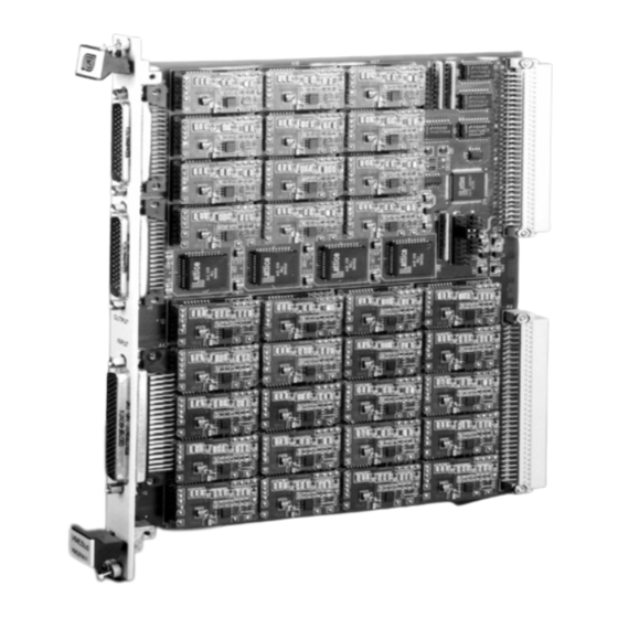
Model VM32PAFF
Programmable Amplifier
32 Channel VME Module
With Fixed Frequency Filter
USER'S MANUAL
We hope the information given here will be helpful. The information is based on data and our best knowledge, and we consider the information to be true and accurate. Please read all
statements, recommendations or suggestions herein in conjunction with our conditions of sale which apply to all goods supplied by us. We assume no responsibility for the use of these
statements, recommendations or suggestions, nor do we intend them as a recommendation for any use which would infringe any patent or copyright.
1
1784 Chessie Lane., Ottawa, IL 61350 • Tel: 800/252-7074, 815/434-7800 • FAX:815/434-8176
e-mail: sales@freqdev.com • Web Address: http://www.freqdev.com
Advertisement
Table of Contents

Related Manuals for Frequency Devices VM32PAFF


Summary of Contents for Frequency Devices VM32PAFF
- Page 1 Model VM32PAFF Programmable Amplifier 32 Channel VME Module With Fixed Frequency Filter USER’S MANUAL We hope the information given here will be helpful. The information is based on data and our best knowledge, and we consider the information to be true and accurate. Please read all statements, recommendations or suggestions herein in conjunction with our conditions of sale which apply to all goods supplied by us.
-
Page 2: Table Of Contents
7. Warranty Information ..........................20 Limitation of Liability..........................20 8. Ordering Guide ............................21 Figures Figure 3-1: VM32PAFF Simplified Functional Block Diagram................6 Figure 3-2 (a) and (b): A daughter module.....................7 Figure 4-1: VM32PAFF Base Address Configuration Jumpers..............10 Figure 4-2: VM32PAFF Front Panel ......................12 Figure 5-1: VM32PAFF VMEbus Memory Map. -
Page 3: Introduction
With Fixed Frequency Filter Introduction The VM32PAFF VMEbus family of amplifier/filter boards from Frequency Devices Inc. offer up to thirty-two channels of software programmable differential input amplifiers combined with precision 3-pole fixed frequency Butterworth or Bessel linear analog filters on each channel. The boards are available in a single width B-size (6U) VME form factor and fully conform to VME Revision C.1 as an A16/D16 Slave. -
Page 4: Specifications
Model VM32PAFF 32 Channel VME Module Programmable Amplifier Specifications With Fixed Frequency Filter Specifications (@ 25 o C and Rated Power Input) Analog Input 1. Input Impedance 1 MΩ//22 pF 2. Maximum Input ±15V 3. AC Couple (Optional) Fixed frequency @ 10Hz Analog Output 4. -
Page 5: Description
With Fixed Frequency Filter Description The VM32PAFF is a single width B-size (6U) VME model that consists of a motherboard and up to 32 daughter modules. The motherboard contains the VMEbus interface and input and output connections. Each daughter module is made up of two boards: a high precision programmable gain amplifier board and a 3-pole filter/buffer amplifier combination board. -
Page 6: Figure 3-1: Vm32Paff Simplified Functional Block Diagram
The programmable gain amplifiers (PGA) are located on daughter modules, see Figure 3-2. There is one PGA for each channel, up to a maximum of 32 channels per VM32PAFF. The input to the gain amplifier is a precision instrumentation amplifier that provides a high impedance differential input with high common mode rejection capability. -
Page 7: Programmable Gain Amplifiers
Model VM32PAFF 32 Channel VME Module Programmable Amplifier Description With Fixed Frequency Filter VMEBus Interface Output Amplifier Ch x IN Ch x OUT 3-pole Low Pass Differential Input PGA Filter Figure 3-2 (a) and (b): A daughter module. X represents the channel number of 1 up to 32. -
Page 8: Hardware Preparation
Use proper GROUNDING TECHNIQUES when handling the board. Carefully remove the VM32PAFF board from its anti-static bag and visually inspect for evidence of damage. If the board appears to be damaged in any way, notify the shipping carrier immediately. 1784 Chessie Lane., Ottawa, IL 61350 • Tel: 800/252-7074, 815/434-7800 • FAX:815/434-8176... -
Page 9: Hardware Configuration
Base Address can be set throughout all of A16 space. A VM32PAFF board occupies a 64-byte block in A16 address space and may be configured on any 64-byte boundary. The user will need to set a Base Address that is appropiate for the VME system in which the VM32PAFF will be installed. -
Page 10: Figure 4-1: Vm32Paff Base Address Configuration Jumpers
Hardware Preparation With Fixed Frequency Filter Figure 4-1: VM32PAFF Base Address Configuration Jumpers. An installed jumper sets a logic '1' while a missing jumper sets a logic '0'. 1784 Chessie Lane., Ottawa, IL 61350 • Tel: 800/252-7074, 815/434-7800 • FAX:815/434-8176... -
Page 11: Board Installation
The board does not use VMEbus interrupts or bus mastering capabilities, but passes all VMEbus daisy chained signals automatically. The major considerations in locating the VM32PAFF board in the mainframe are for EMI and I/O signal cabling. To minimize interference from other boards in the system, it is good practice to keep one or more empty slots between analog signal conditioning boards and high speed digital boards in the system. -
Page 12: Figure 4-2: Vm32Paff Front Panel
Hardware Preparation With Fixed Frequency Filter VM32PAFF Figure 4-2: VM32PAFF Front Panel The analog input connector is a female 78-pin D-shell connector. The analog output connectors are two male 44-pin D-shell connectors. 1784 Chessie Lane., Ottawa, IL 61350 • Tel: 800/252-7074, 815/434-7800 • FAX:815/434-8176... -
Page 13: Connector/Cable Information And I/O Connections
Table 4-1: Analog Input Connections. Refer to Figure 4-2 for connector orientation. The mating connector is a male high-density 78-pin D-sub . Frequency Devices recommends that input signals be wired using cable consisting of individually shielded twisted pairs of #22 AWG stranded wire. -
Page 14: Table 4-2: Analog Output Connections
Refer to Figure 4-2 for connector orientation. The mating connectors are female high-density 44-pin D- subs. Frequency Devices recommends that output signals be wired using cable consisting of individually shielded twisted pairs of #22 AWG stranded wire. 1784 Chessie Lane., Ottawa, IL 61350 • Tel: 800/252-7074, 815/434-7800 • FAX:815/434-8176... -
Page 15: Programming
Programming Register Level Programming A register-based read/write programming interface makes the VM32PAFF family of VMEbus amplifier/filter boards extremely easy to program. All the programmable gain modules on the motherboard may be programmed through three 16-bit registers. These are the Channel Address Register, the Data Register, and the Reset Register. -
Page 16: Table 5-1: Data Register Gain Settings
Model VM32PAFF 32 Channel VME Module Programmable Amplifier Programming With Fixed Frequency Filter The Channel Address Register or CHADR (located at Base Address + 0) holds the address of the daughter module being addressed. The first amplifier channel, Channel 0, has an address of (00)x and the last amplifier channel, Channel 31, has an address of (1F)x. -
Page 17: Programming Procedure
Once the desired channel has been selected, the user then sets that channel’s gain by writing the desired gain data to DATA (Base Address + 2). The VM32PAFF automatically sets the BUSY bit in the CHADR register to indicate that the serial bus is transferring data. The BUSY bit is automatically cleared once the transfer is complete. - Page 18 Model VM32PAFF 32 Channel VME Module Programmable Amplifier Programming With Fixed Frequency Filter • Reading the Data Register while BUSY is set will yield erroneous data but will not impair board operation or contaminate any channel settings. This event is not flagged, so it is important to use the BUSY interlock before reading the Data Register.
-
Page 19: Troubleshooting And Technical Support
Inrformation Troubleshooting and Technical Support If you have difficulty installing the VM32PAFF board, or if the board fails to operate properly, contact Frequency Devices for technical assistance. Technical assistance is available weekdays 8:00 AM to 4:30 PM Central time at 815-434-7800 or 800-252-7074. Inquiries may also be faxed to 815-434-8176 or emailed to sales@freqdev.com. -
Page 20: Warranty Information
Model VM32PAFF 32 Channel VME Module Programmable Amplifier Warranty Information With Fixed Frequency Filter Warranty Information Unless otherwise specified in writing by FDI, all FDI products sold hereunder are warranted against defects in workmanship and material under normal use and service for a period of one (1) year from the date of... -
Page 21: Ordering Guide
With Fixed Frequency Filter Ordering Guide VM32PAFF Ordering Guide For flexibility in many applications the Frequency Devices VM32PAFF VMEbus Board may be ordered with 8, 16, or 32 amplifier/filter modules. Figure 4-1 indicates the location of each channel. Transfer Function...
Need help?
Do you have a question about the VM32PAFF and is the answer not in the manual?
Questions and answers