Sign In
Upload
Download
Table of Contents
Contents
Add to my manuals
Delete from my manuals
Share
URL of this page:
HTML Link:
Bookmark this page
Add
Manual will be automatically added to "My Manuals"
Print this page
×
Bookmark added
×
Added to my manuals
Manuals
Brands
Fogo Montanha Manuals
Stove
T300
Instruction manual
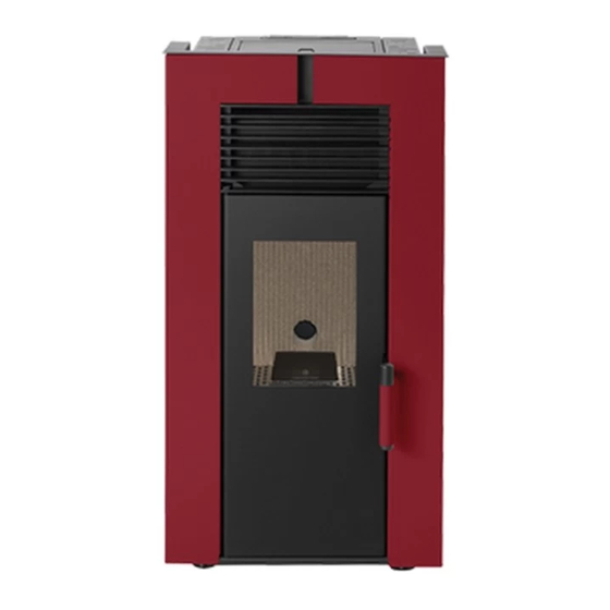
Fogo Montanha T300 Instruction Manual
Hide thumbs
1
Table Of Contents
2
3
4
5
6
7
8
9
10
11
12
13
14
15
16
17
18
19
20
21
22
23
24
25
26
27
28
29
30
31
32
33
34
35
36
37
38
39
40
41
42
43
44
45
46
47
48
49
50
51
52
53
54
55
56
57
58
59
60
61
62
63
64
65
66
67
68
69
70
71
72
73
74
75
76
77
78
79
80
81
82
83
page
of
83
Go
/
83
Contents
Table of Contents
Bookmarks
Table of Contents
Table of Contents
Important Aspects
Features
Fuel
Installing Ducts and Fume Extraction Systems
Installing Without a Chimney
Installing with a Chimney
Package Content
Safety
Installing the Pellet Burning Free Standing Fire
Filling the Pellet Reservoir
Remote Control and Display Panel
Humidifier
Activation
Disabling
Recommendations on Using this Unit
Cleaning and Maintenance
Heat Exchanger
Burning Basket and Ash Pan Grate
Ash Basket
Trapdoor
Cleaning the Glass
Additional Cleaning
Performing an Inspection after a Long Period of Inactivity
Maintenance Guide Label
Display
Keyboard Settings - Select Language
Keyboard Settings - Date / Time
Keyboard Menu
Personalisation Menu
Chrono
User Info
Product Code
Anomalies
List of Alarms / Failures / Recommendations
Instruction for Installing the T300 and T400 Casings
Instruction for Installing the T500 Casings
Installing the Ductable Air (Article Code: PA1090G030 Optional Only T500)
Electrical Connections
Adjustable Ductable Air Inlet
Recommendations for the Installation of the Ductable Air (T500)
Installing and Operating with Thermostat Chrono - Optional
Instructions to Assemble the Remote Control
Installing Safety Optional - UPS Connection Kit
For Your Security We Remind You that
Life Cycle of a Free-Standing Fire Unit
Sustainability
Warranty
Annexes
Statement of Performance
Advertisement
Quick Links
Download this manual
Instruction Manual
T300 Frame 8kW
T400 Frame 10kW
T500 Tube 9kW
Mod. 835-E
Table of
Contents
Previous
Page
Next
Page
1
2
3
4
5
Advertisement
Table of Contents
Need help?
Do you have a question about the T300 and is the answer not in the manual?
Ask a question
Questions and answers
Subscribe to Our Youtube Channel
Related Manuals for Fogo Montanha T300
Stove Fogo Montanha T500 Instruction Manual
(83 pages)
Stove Fogo Montanha Round Instruction Manual
Firewood round stove (35 pages)
This manual is also suitable for:
T400
T500
Table of Contents
Print
Rename the bookmark
Delete bookmark?
Delete from my manuals?
Login
Sign In
OR
Sign in with Facebook
Sign in with Google
Upload manual
Upload from disk
Upload from URL


Need help?
Do you have a question about the T300 and is the answer not in the manual?
Questions and answers