Table of Contents
Advertisement
AC Servo Driver Manual
● Thank you very much for your purchasing our HA-675 series
servo driver.
● Be sure to use sufficient safety measures when installing and
operating the equipment so as to prevent an accident resulting in
a serious physical injury damaged by a malfunction or improper
operation.
● Product specifications are subject to change without notice for
improvement purposes.
● Keep this manual in a convenient location and refer to it
whenever necessary in operating or maintaining the units.
● The end user of the driver should have a copy of this manual.
HA-675 Series
SOFTWARE Ver.2.1
ISO14001
ISO9001
Advertisement
Table of Contents
Troubleshooting

Subscribe to Our Youtube Channel
Related Manuals for Harmonic Drive HA-675 Series


Summary of Contents for Harmonic Drive HA-675 Series
- Page 1 HA-675 Series AC Servo Driver Manual ● Thank you very much for your purchasing our HA-675 series servo driver. ● Be sure to use sufficient safety measures when installing and operating the equipment so as to prevent an accident resulting in a serious physical injury damaged by a malfunction or improper operation.
- Page 2 SAFETY GUIDE For actuators, motors, control units and drivers SYSTEMS manufactured by Harmonic Drive Systems Inc Read this manual thoroughly before designing the application, installation, maintenance or inspection of the actuator. Indicates a potentially hazardous situation, Indicates a potentially hazardous situation, which, if...
-
Page 3: Table Of Contents
HA-675 series servo driver manual Contents Chapter 1 Outlines of HA-675 driver ······················································································· 1 Main features············································································································· 1 Models of HA-675 driver···························································································· 2 Combinations with actuators ····················································································· 3 Specifications of HA-675 driver ················································································· 3 External drawing of the HA-675 drivers ···································································· 4 Front panel ················································································································... - Page 4 HA-675 series servo driver manual I/O port connections ································································································ 31 3-3-1 Logical inputs ·········································································································· 31 3-3-2 Contact inputs·········································································································· 31 3-3-3 Outputs ···················································································································· 32 3-3-4 Monitor outputs········································································································ 32 I/O port functions ····································································································· 33 Connection example································································································ 42 I/O ports for absolute position data ABS ································································· 44 3-6-1 General descriptions of absolute encoder·······························································...
- Page 5 HA-675 series servo driver manual 5-2-2 Daily maintenance··································································································· 77 Chapter 6 Operation of the display panel············································································· 78 Summary of modes ································································································· 78 Selecting a mode····································································································· 78 Functions of each mode ·························································································· 79 Monitor mode ·········································································································· 80 6-4-1 Operation in the monitor mode················································································ 80 6-4-2 Functions of the monitor mode················································································...
- Page 6 HA-675 series servo driver manual Chapter 8 Troubleshooting ·································································································· 154 Alarms and diagnostic tips ···················································································· 154 Troubleshooting for improper actuator motion ······················································ 168 8-2-1 No rotation············································································································· 168 8-2-2 Unstable rotation ··································································································· 169 8-2-3 Poor positioning accuracy ····················································································· 171 Exchanging batteries ABS ···················································································· 172 8-3-1 Duration of keeping a revolution count··································································...
-
Page 7: Outlines Of Ha-675 Driver
The HA-675 series provides four modes that can be adjusted by the end user: monitor mode, tune mode, parameter mode, and test mode. Parameters of these modes are indicated on the front panel using a 7-segment LED display and are easily set. -
Page 8: Models Of Ha-675 Driver
Chapter 1 Outlines of HA-675 driver 1-2 Models of HA-675 driver Model number of The HA-675 driver is as follows HA-675-2A-200 AC servo driver HA series 675 series Nominal current 2.4 A Encoder Incremental encoder code Absolute encoder See Note 1. Input voltage 200V 100V... -
Page 9: Combinations With Actuators
Chapter 1 Outlines of HA-675 driver 1-3 Combinations with actuators Five HA-675 models are available for use with FHA-C actuators dealing with their nominal current and encoder systems. The correct combinations are as follows: Model Incremental system INC Absolute system ABS Volt. -
Page 10: External Drawing Of The Ha-675 Drivers
Chapter 1 Outlines of HA-675 driver 1-5 External drawing of the HA-675 drivers The external drawing is shown as follows: Unit: mm (Third angle projection method) Heat sink The dimensions marked with “※” are applied for HA-675-4A only. Ventilation holes Base dimensions Name plate Battery room... -
Page 11: Front Panel
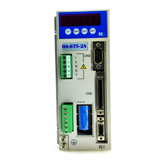
Chapter 1 Outlines of HA-675 driver 1-6 Front panel Names of front panel blocks LED display DOWN key ADJ key UP key SET key Power supply terminal CN3: Serial port connector For control power: r,s (Teach-box connector) HA-675-2 For main power: R,S,T CN2: I/O connector For regeneration resistor: R1,R2 For actuator: U,V,W... -
Page 12: Outlines Of I/O Ports
Chapter 1 Outlines of HA-675 driver 1-7 Outlines of I/O ports The CN2 connector provides input and output signals to and from the host devices. The 50 pins of the connector are assigned to the following signals. Do not connect signals to pins marked “-“. Pin No. -
Page 13: Operating Display Panel
Chapter 1 Outlines of HA-675 driver 1-8 Operating display panel The HA-675 driver provides a 6-digit LED display and four operation keys on the front panel. The panel executes monitoring, tuning, setting, and JOG operation. 1-8-1 Outlines of operation modes The HA-675 driver provides the following four modes: monitoring, tuning, setting, and operations. -
Page 14: Functions Of Each Mode
Chapter 1 Outlines of HA-675 driver 1-8-3 Functions of each mode Each mode provides the following functions: Mode Code Function Setting & operation Current address Motor speed Error pulse count (Low) Error pulse count (High) Torque monitor Overload rate Feedback pulse (Low) Monitor mode Setting is impossible. -
Page 15: External Drawing Of The Teach-Box
Chapter 1 Outlines of HA-675 driver 1-9-2 External drawing of the teach-box The external drawing is shown as follows: Unit: mm (Third angle projection method) 120 (MAX) 50 (MAX) S O N E S T P D E N B ABSREQ ABSCLR It is possible to add a commercially available EIA-232C (RS-232C) cable to extend the 2-meter teach-box cable. -
Page 16: Main Blocks Of The Teach-Box Panel
Chapter 1 Outlines of HA-675 driver 1-9-3 Main blocks of the teach-box panel The teach-box panel consists of four blocks as follows: LCD display Emergency stop switch Mode LED S O N E S T P D E N B ABSREQ ABSCLR Operation keys The operating data can be set in the following unit. -
Page 17: Operation Keys
Chapter 1 Outlines of HA-675 driver 1-9-4 Operation keys The teach-box provides three operation modes: [program], [test] and [parameter]. The functions of a key are different by the modes. The relation between keys and functions are as follows: Operation mode Program mode Test mode Parameter mode... - Page 18 Chapter 1 Outlines of HA-675 driver Mode Program mode Test mode Parameter mode INC increments, ABS positions Sets a speed changing position. Divides equally a positional value of POS command. Repeats the motion from specified address to the preceding address having LOP. End of a motion program.
-
Page 19: Operation Modes
Chapter 1 Outlines of HA-675 driver 1-9-5 Operation modes Three modes are provided for teach-box operation as follows: ◆ Program mode In the mode you can create motion programs using commands of position, speed, acceleration time, delay time, jump, indexing, repeat and so on. ◆... -
Page 20: Outlines Of Protection Functions
Chapter 1 Outlines of HA-675 driver 1-10 Outlines of protection functions 1-10-1 Alarms HA-675 drivers provide various functions to protect actuators and drivers from the occurrence of abnormalities. When a function detect faults, the actuator enters a free rotation state, a two-digit alarm code is indicated on the display, and a set of 4-bit alarm signals is transmitted to the host. -
Page 21: Protection Functions
Chapter 1 Outlines of HA-675 driver 1-10-2 Protection functions The HA-675 driver provides the following alarms to protect the servo system. ◆ Emergency stop (01) When an emergency stop signal [OFF] comes to [CN2-15, -16 emergency stop: ESTOP] from a host, or when the emergency stop switch on the teach-box is pressed, the alarm occurs. - Page 22 Chapter 1 Outlines of HA-675 driver ◆ Over voltage (40) The alarm occurs for HA-675-1 only. It occurs when the main circuit voltage exceeds about 390V. The HA-675-1 drivers do not equip regeneration resistors to absorb regenerated energy at deceleration. When the load inertia is very big (example: 6 times or more of inertia of FHA-14C), the voltage of servo circuit increases highly and the alarm occurs.
- Page 23 Chapter 1 Outlines of HA-675 driver ◆ Revolution count error (55) ABS While the absolute encoder is not supplied power by power supply but the encoder circuit is active only by the power of a built-in condenser and a built-in battery, the alarm occurs when the encoder rotates too fast at the acceleration rate and/or speed exceeding the allowed zone shown the figure below.
-
Page 24: Functions
Chapter 2 Functions Chapter 2 Functions 2-1 Control system of HA-675 driver It is said that [plan, do, see] is essential to perform Perfect job cycle perfect jobs. In other words, the [plan, do, see] is the repeating cycle of command→action→result→feedback →modified command→action→feedback→・・・・. -
Page 25: Encoder System
Chapter 2 Functions 2-2 Encoder system The HA-675 driver allows to select an encoder as a functional member of the feedback system from two types: an incremental encoder and an absolute encoder. Phase-A detector 2-2-1 Incremental encoder Phase-B detector Phase-A emitter Phase-B emitter The incremental encoder outputs pulses Phase-Z detector... -
Page 26: Tuning Servo Gains
Chapter 2 Functions 2-3 Tuning Servo gains The HA-675 driver is fed back position and speed signals as follows: Driven machine HA-675 driver Position Actuator Position Speed control Power command block control block block amplifier Speed loop Speed feedback Position loop Encoder Position feedback In the figure, the closed loop of [speed control block]→[power amplifier]→[actuator]→[encoder]→... -
Page 27: Speed Control Block, Speed Loop Gain, And Speed Loop Integral Compensation
Chapter 2 Functions 2-3-2 Speed control block, speed loop gain, and speed loop integral compensation (1) The first function of the [speed control block] is to subtract a feedback signal from a command signal. (2) The second function is the block converts the difference to a [current command] multiplies it by the factor, and then transmits the [current command (I)] to the [power amplifier]. -
Page 28: Motion Control Functions
Chapter 2 Functions 2-4 Motion control functions You can create motion programs with the teach-box having operation keys and a LCD display without any complicated operation. 2-4-1 Outlines of teach-box The teach-box provides a LCD display of 4 lines by 20 digits, a push-lock emergency-stop switch, 44 operation keys, and three LED indicators. -
Page 29: Outlines Of Programming
Chapter 2 Functions 2-4-2 Outlines of programming ● Program format For motion programs of an actuator the HA-675 driver may store up to 64 addresses which consist of commands such as stop position, speed changing position, speed, acceleration time, delay time, indexing, jump, repeat cycle, and so on. - Page 30 Chapter 2 Functions ● Command The commands of program mode are divided into two groups: ◆ Motion commands: This group relates to actuator motion profile. The commands are programmed in the addresses having a position. SPD: speed POS: INC increments, ABS positions CHP: speed changing position SLP:...
- Page 31 Chapter 2 Functions ● Acceleration and deceleration profile Speed Linear acceleration The HA-675 driver provides two acceleration profiles: the linear acceleration profile and the S-curve acceleration profile. The S-curve acceleration is available only for single Time speed profiles, not for compound speed profiles programmed with the [CHP] command.
- Page 32 Chapter 2 Functions ● Origination To create and execute motion programs, it is necessary to establish an origin as the base point of the motion. The HA-675 driver allows to set an origin from three kinds as follows: (1) encoder phase-Z position: has high repeatability, needs long originating time of maximum 20 sec. (2) origin sensor position: has low repeatability, needs shorter originating time.
-
Page 33: Other Functions
Chapter 2 Functions ◆ Current position as the mechanical origin INC For the incremental system, this is the way for the system having no origin sensor requiring no repetitive positions. This is not available for the absolute position. (1) Turn on the [CN2-4 originating: ST-ORG] holding ON state of [CN-5 Interlock: INTERLOCK]. (2) After 2ms or more, turn off the [CN2-4 originating: ST-ORG]. -
Page 34: Error Count Clear By S-On
Chapter 2 Functions 2-5-4 Error count clear by S-ON The HA-675 driver controls a motor so that the error count is always [0] during the servo power is active. However, when the servo power is shut down turning off the input of [CN-2-3 servo ON: S-ON] and only the control power is active, the error count may not be [0] proportioning to movement by external force, such as gravitational force and human power, from the position where the servo power is shut down. -
Page 35: Automatic Actuator Identification For Ha-675-1 Driver
Chapter 2 Functions 2-5-6 Automatic actuator identification for HA-675-1 driver The function is available when an HA-675-1 driver and an FHA-8C/11C/14C actuator are connected correctly. Following power supply turning-ON to the driver after connecting with the actuator; (1) the driver identifies the code of the actuator connected to it automatically, and (2) if the identified code is different from a registered code, the newly identified code takes place of the registered code, and values of some parameters of the parameter mode and the tune mode are switched to initial values for the newly connected actuator. -
Page 36: I/O Ports
Chapter 3 I/O ports Chapter 3 I/O ports The CN2 connector provides input and output signals to and from the host devices. The 50 pins of the connector are assigned to the following signals. Do not connect signals to pins marked “-“. 3-1 I/O port layout The I/O port layout is shown as follows: Pin No. - Page 37 Chapter 3 I/O ports 3-3 I/O port connections This section describes the connection between the I/O ports and a host. Ext. Power +24V 2.2K 3-3-1 Logical inputs The HA-675 driver provides 14 ports for ABS Position ABS-REQ logical inputs as shown in the figure to the data request right.
-
Page 38: Outputs
Chapter 3 I/O ports 3-3-3 Outputs READY Ready The HA-675 driver provides 11 ports of 10 signals for inputs as shown in the figure to the right. FINISH Motion finish ● Specifications ORG-END At-origin Port: Open collector Voltage: DC24V or less ALARM Alarm Current: 40mA or less (per port) -
Page 39: I/O Port Functions
Chapter 3 I/O ports 3-4 I/O port functions This section describes I/O port functions. CN2-1 Input signal common: INPUT-COM (input) ● Function This is the common port for inputs: [CN2-2 to 7, 9 to 14]. Supply external power for inputs to this port. ●... - Page 40 Chapter 3 I/O ports CN2-5 Interlock: INTERLOCK (input) ● Function The input (ON) to the port stops actuator motion immediately. Turning OFF the input restarts actuator motion. As this port activates by [NO-contact signal (a-contact)], do not use this port for safety circuit. The input (ON) to the [CN2-6 start: START] will be ignored.
- Page 41 Chapter 3 I/O ports CN2-9 to 14 Input bit: INPUT-DATA (input) ● Function A set of six ports specifies a start address of programming motion with a 6-bit pattern. The relation between addresses and inputs are as follows; 2-14 2-13 2-12 2-11 2-10...
- Page 42 Chapter 3 I/O ports CN2-17, 18 FWD limit: FSTOP (input) CN2-19, 20 REV limit: RSTOP (input) ● Function The [CN2-17, 18 FWD limit: FSTOP] accepts the forward-side limit sensor signal, and [CN2-19, 20 REV limit: RSTOP] accept the reverse-side limit sensor signal. When either port turns OFF (input), the actuator stops with deceleration.
- Page 43 Chapter 3 I/O ports CN2-23 Speed monitor: SPD-MON (output) ● Function The port outputs a voltage signal proportional to the motor speed. Note that the voltage signal is not outputted during JOG operation, and is unstable until outputting the signal of [CN2-33 ready: READY] after activating power supply.
- Page 44 Chapter 3 I/O ports CN2-26 +24V: +24V (input) CN2-28 Position data request: ABS-REQ (input) ● Function This is used for a command to output a current resolving count of the encoder. The [CN2-44, 45 phase-A: A+, A-] and [CN2-46, 47 phase-B: B+, B-] output the current count. The function is available only one time after power ON.
- Page 45 Chapter 3 I/O ports CN2-34 Motion finish: FINISH (output) ● Function The HA-675 driver outputs the signal when the actuator completes the specified motion and an error count comes in the range of [tune mode]→[4: in-position range]. The signal will be reset by the next start signal.
- Page 46 Chapter 3 I/O ports CN2-37 to 42 Output bit: OUT-DATA (output) ● Function A set of six ports outputs the motion complete address with a 6-bit pattern. The relation between addresses and outputs are as follows; 2-42 2-41 2-40 2-39 2-38 2-37 2-42...
- Page 47 Chapter 3 I/O ports ● Connection HA-675 (1) An example of [CN2-37 Output bit 1: OUT-DATA TLP127 CN2-37 OUT-DATA1 1] connection is shown in the figure to the right. (2) Plan the output circuit for the ports as follows: CN2-43 OUT-COM Supply voltage: +24V or less...
-
Page 48: Connection Example
Chapter 3 I/O ports 3-5 Connection example << for incremental system >> INC ◆ The figure below shows a connection example for the incremental system. HA-675-*-*** Line filter INPUT-COM DC24V Ext. power 2.2k CLEAR Clear 2.2k S-ON Transformer Servo-ON Line filter 2.2k ST-ORG Originating... - Page 49 Chapter 3 I/O ports << for absolute system >> ABS ◆ The figure below shows a connection example for the absolute system. HA-675-*A-*** 2.2k Line filter +24V 2.2k DC24V Ext. power ASB-REQ ABS Position data Transformer Line filter request ASB-CLEAR Power AC200V INPUT-COM...
-
Page 50: I/O Ports For Absolute Position Data Abs
Chapter 3 I/O ports 3-6 I/O ports for absolute position data ABS 3-6-1 General descriptions of absolute encoder The absolute encoder mounted on the FHA-C series actuator controls the position data with “Single revolution data” to control the absolute position Photo detector within a revolution and “Revolution data”... -
Page 51: Outputting Position Data From Output Port: Cn2
Chapter 3 I/O ports 3-6-2 Outputting position data from output port: CN2 Following the powering sequence, the ports of the [CN2-44 phase-A: A+] through [CN2-49 phase-Z: Z-] output pulse trains for the current position data just for once, automatically or by responding to the [CN2-28 position data request: ABS-REQ]. -
Page 52: Installing The Ha-675 Driver
Chapter 4 Installing HA-675 driver Chapter 4 Installing the HA-675 driver 4-1 Receiving Inspection Check the followings when products are received. ● Inspection procedure (1) Check the shipping container and item for any damage that may have been caused during transportation. -
Page 53: Notices On Handling
Chapter 4 Installing HA-675 driver 4-2 Notices on handling The HA-675 drivers are electronic devices. Handle them with care and take the following precautions: (1) Do not drop screws, solder balls, wire chips, or any other foreign objects through the ventilation gaps of the HA-675 driver. -
Page 54: Location And Installation
Chapter 4 Installing HA-675 driver 4-3 Location and installation 4-3-1 Environment of location The environmental conditions of the location are as follows: ◆ Service temperature: 0 deg. C to 50 deg. C Use the driver in a cabinet. The temperature in the cabinet may be higher than the atmosphere because of power loss of the housed devices and its size. -
Page 55: Installing
Chapter 4 Installing HA-675 driver 4-3-3 Installing The HA-675 driver should be mounted on a wall as shown in the figure to the right. Two mounting holes are provided on the back of the driver. The thickness of the wall should be more than 2mm. -
Page 56: Installing Noise Filter
Chapter 4 Installing HA-675 driver ◆ Grounding motor frame When actuators are grounded at driven machine through the motor frame, current flows through floating capacity (Cf) of the motor from power amplifier of the driver. To avoid influence of the current, always connect the ground terminal (motor frame) of the motor to the ground terminal of the driver, and connect the ground terminal of the driver to the ground directly. -
Page 57: Instructions For Cabling
Chapter 4 Installing HA-675 driver 4-4-3 Instructions for cabling In addition to the noise suppression mentioned previously, follow these instructions as well: (1) Use twisted pair cables for I/O signals, and for encoder signals cables. When a host controls several drivers, prepare I/O signal cables for each driver individually. (2) Make the length of signal cables as short as possible. -
Page 58: Connecting Power Cables
Chapter 4 Installing HA-675 driver 4-5 Connecting power cables 4-5-1 Instructions for power supply Before connecting the power cable to the HA-675 driver, completely take the power cable off from the main power. Failure to observe this caution may result in electric shock during the WARNING work. -
Page 59: Connecting The Power Cable
Chapter 4 Installing HA-675 driver 4-5-3 Connecting the power cable The terminal block for the power is located on the front panel of the HA-675 driver. There is no phase order in connection to three-phase power lines. Shown the figure to the right, strip the end of wires of the power supply cable and the motor cable, and connect wires to each terminal firmly. -
Page 60: Protecting Power Lines
Chapter 4 Installing HA-675 driver 4-5-5 Protecting power lines We recommended protecting the driver by installing a circuit breaker or fuses from surge current at power-ON. Select the recommended circuit breakers or fuses using the table below. FHA-8C,-11C FHA-14C FHA-17C FHA-25C FHA-32C FHA-40C... -
Page 61: Connecting The Encoder And The I/O Cables
Chapter 4 Installing HA-675 driver 4-8 Connecting the encoder and the I/O cables 4-8-1 Preparing the encoder cable and the I/O cable Follow these instructions for the preparation of the encoder cable and the I/O cable. (1) Use twisted pair cables for I/O signal cables and for encoder signal cables. When a host controls several drivers, install I/O signal cables for each driver individually. -
Page 62: Pin Layouts Of The I/O Signal Connector (Cn2)
Chapter 4 Installing HA-675 driver 4-8-3 Pin layouts of the I/O signal connector (CN2) The models and the pin layout of the encoder connector are as follows: Plug: model: 10150-3000PE manufacturer: 3M Shell: model: 10350-52F0-008 manufacturer: 3M ◆ Pin layout ORG- RSTOP FSTOP... -
Page 63: Power On And Off Sequences
Chapter 4 Installing HA-675 driver 4-9 Power ON and OFF sequences 4-9-1 Power ON / OFF sequence circuit Plan the sequence circuit to operate the switch for main power individually by an [emergency stop] signal and the [CN2-36 alarm: ALARM] signal of the HA-675 driver. Make switching operation (turning ON or OFF) at the state that the [CN2-3 servo-ON: S-ON] is OFF. -
Page 64: Power Off Sequence
Chapter 4 Installing HA-675 driver ◆ Power ON sequence for absolute system ABS Control power OFF⇒ON 0ms(min) Main power OFF⇒ON 4s(max) CN2-33 Ready: READY outputting 3ms(max) CN2-36: Alarm: ALARM outputting 0ms(min) Note1: For the setting [1: at control Note 1 10ms(max) power-ON] for [H: ABS data request timing], the signal in the... -
Page 65: Operations
Chapter 5 Operations Chapter 5 Operations Follow these instructions prior to operations. When electric power is active, do not make any wiring works. In advance of wiring work, shut off electric power supply to be free from electric shock. WARNING 1. - Page 66 Chapter 5 Operations Procedure of trial run For HA-675-1 drivers to drive FHA-C mini(FHA-8C/11C/14C) actuators, start with the procedure (1). For HA-675-2/4 specifying the incremental system, start with the procedure (4). For HA-675-2/4 specifying the absolute system, start with the procedure (5). ◆...
- Page 67 Chapter 5 Operations ★ When identified code is different from the pre-registered code; ⇒ The indication (monitor mode) to the right appears Indication for different codes on the display of the HA-675 driver showing [cH] and identified code. The identified code is different from the pre-registered code.
- Page 68 Chapter 5 Operations ◆ Power-ON procedures for absolute system. ABS For the absolute system, following operations are required at the first stage. a. Clearing revolution counter at first power-ON* * When you connect the HA-675 driver and the actuator delivered from us and turn on the power for the first time, you will have a “53: System down”...
- Page 69 Chapter 5 Operations <<Transmitting position data>> (10) Turn on the control power pressing both [ADJ] and [SET] keys in same time again. Leave fingers from keys after indicating. ⇒ Enters into the [parameter mode]. (11) Indicate [H] (ABS send data timing) using keys of D O W N A D J S E T...
- Page 70 Chapter 5 Operations ◆ Manual JOG operation of the actuator (19) To enter into the [test mode] from the [monitor mode], press the [SET] key at least three seconds. ⇒ Indicates 6th to 4th digit in the order, and enters the [test mode] when there is no indication on 4th to 6th digit.
- Page 71 TBX-670. Terminate the [test mode] once before the JOG operation. AC Servo Controller HA-675 Ver __. __ Press keys of the teach-box Harmonic Drive Systems one by one surely. Pressing two or more key at a time may indicate [Over-run...
- Page 72 Chapter 5 Operations ◆ Verifying Input signals 1st digit 6th digit Note: Enter the [test mode] again after the JOG operation. (32) Indicate [c: I/O monitor] by pressing the [UP] or [DOWN] key. The third and forth digit indicates output states and the fifth and sixth indicates input states.
- Page 73 Chapter 5 Operations ◆ Verifying output signals (34) Indicate [rdy: output port operation] by pressing the [UP] or [DOWN] key. (35) To operate output ports, press the [ADJ] key for 0.1second or more. D O W N A D J S E T D O W N A D J...
-
Page 74: Setting Parameters
Chapter 5 Operations 5-1-2 Setting parameters After the actuator trial run you may begin setting the parameters via the parameter mode. All parameters are dependent upon the driven machine system. The abstracts of the parameters in the parameter mode are described in the table below: Name Description Parameters... - Page 75 Chapter 5 Operations (44) Press [UP] or [DOWN] key to change the functional items of the parameter mode. D O W N A D J S E T Function selection (45) To change a value, press [ADJ] key for 0.1 second or more.
-
Page 76: Tuning Servo Parameters
Chapter 5 Operations 5-1-3 Tuning servo parameters After setting the parameters of [parameter mode], couple the actuator with the driven machine; and you may start tuning the servo parameters. Usually it is not necessary to tune the parameters, because these servo parameters have been set to the proper values for the actuator as standard defaults. - Page 77 Chapter 5 Operations (55) To change a value, press [ADJ] key for 0.1 second or more. ⇒ 1st digit [0] flickers. You can change the value. (56) Change the value with the [UP] and [DOWN] keys. [UP] key increases the value. [DOWN] key decreases the value.
-
Page 78: Operations Of Teach-Box
AC Servo Controller HA-675 Ver __. __ The next stage of set-up operation is parameter setting in the teach-box. Harmonic Drive Systems (60) Attach the connector of the teach-box to the CN3 socket of the HA-675 driver. ⇒ After the connection, the display indicates the Press any key. -
Page 79: Setting Parameter Data
Chapter 5 Operations ◆ Correcting the entering data (67) To correct the entering data, press [CANCEL] key. ⇒ The entering data is canceled. ERASE OK ? (68) After the erasing, enter the new correct data. DSET pps pls No 00 ◆... - Page 80 Chapter 5 Operations ● Setting parameters for origination To create and execute motion programs, it is necessary to establish an origin as the base point of the motion. The HA-675 driver allows to set an origin from three kinds as follows: (1) current position INC: for the system having no origin sensor requiring (2) encoder phase-Z position: has high repeatability, needs long originating time of maximum 20 sec.
- Page 81 Chapter 5 Operations Fix tightly the origin sensor and a dog for the sensor. Loosen fixing may cause unstable origin in its position. And attaching the origin sensor at close position to the encoder phase-Z may also CAUTION cause unstable origin. Leave both positions with each other. ◆...
-
Page 82: End Of Trial Run
Chapter 5 Operations ◆ Origin sensor as the mechanical origin (77) To define the origin sensor as the origin, set 1: origin sensor] to [parameter mode] →[G: mechanical origin]. <<The start position is between the FWD limit and the origin sensor.>> ≪Mechanical origin≫... -
Page 83: Normal Operation
Chapter 5 Operations 5-2 Normal operation As the HA-675 driver runs by commands from a host, no special intervention is required for normal operations. In this section, instructions for daily operations and maintenance are explained. 5-2-1 Notices for normal operations 1. -
Page 84: Operation Of The Display Panel
Chapter 6 Operations of display panel Chapter 6 Operation of the display panel The display panel of the HA-675 driver is equipped with a six-digit LED display and four operation keys. Monitoring information, tuning operations, setting operations, and jog operation are done using the display panel. -
Page 85: Functions Of Each Mode
Chapter 6 Operations of display panel 6-3 Functions of each mode Each mode provides the following functions: Mode Code Function Setting & operation Current address Motor speed Error pulse count (Low) Error pulse count (High) Torque monitor Overload rate Feedback pulse (Low) Monitor mode Setting is impossible. -
Page 86: Monitor Mode
Chapter 6 Operations of display panel 6-4 Monitor mode The HA-675 driver displays a current address number, motor speed, current position from a motor-encoder, pulse count in an error counter, input and output signal states, load condition, alarm history, and the code number for the actuator for which the driver is set. These are useful to diagnose the driver if it fails or operates in an abnormal manner. -
Page 87: Functions Of The Monitor Mode
Chapter 6 Operations of display panel 6-4-2 Functions of the monitor mode Current address 1st digit 6th digit ● Function The “current address” indicates the currently executing address or the address just executed. D O W N A D J S E T ●... - Page 88 Chapter 6 Operations of display panel [Monitor mode] Error pulse count (low) 1st digit 6th digit ● Function The fundamental functions of servomotors are for positioning and rotating responding to a command signals. A block diagram of servo motor control is shown as follows: Error counter HA-675 D O W N...
- Page 89 Chapter 6 Operations of display panel [Monitor mode] Torque Monitor 1st digit 6th digit ● Function This indicates current output torque of the actuator in “%” where “100%” corresponds to the maximum torque. ● Details of display D O W N A D J S E T 1st digit:...
- Page 90 Chapter 6 Operations of display panel [Monitor mode] Feedback pulse (Low) 1st digit 6th digit ● Function The fundamental functions of servomotors are positioning and rotation responding to a command signal. A block diagram of servo motor control is shown as follows: HA-675 Error counter D O W N...
- Page 91 Chapter 6 Operations of display panel [Monitor mode] I/O monitor 1st digit 6th digit ● Function The display indicates input/output signal states of [CN2] connector pins as follows: Output signals: Third and forth igits Input signals: Fifth and sixth digits Each element of both 7-segment indicators lights up when D O W N A D J...
- Page 92 Chapter 6 Operations of display panel [Monitor mode] Alarm history ● Function 1st digit 6th digit The “alarm history” indicates up to eight previous alarms with codes. ● Details of display 1st digit: [d: alarm history] 2nd digit: The order of the indicated alarm: [1] indicates the latest alarm, D O W N A D J...
- Page 93 Chapter 6 Operations of display panel [Monitor mode] Actuator code ● Function 1st digit 6th digit This indicates the code of the HA-675 driver is set for. The relation of the codes and actuators is as follows: Do not connect an actuator that D O W N A D J S E T...
- Page 94 Chapter 6 Operations of display panel [Monitor mode] Actuator serial number (Low) (position / speed) Actuator serial number (High) (position / speed) Actuator serial number (Affix) (position / speed) ● Function A set of the three parameters; [F: actuator serial number (low), [G: actuator serial number (high), and [H: actuator serial number (affix) D O W N...
-
Page 95: Tune Mode
Chapter 6 Operations of display panel 6-5 Tune mode The tuning mode consists of various parameters to control the actuator motion. Setting the most suitable value for each parameter will ensure the optimum performance of the actuator. The [tune mode] indicates and sets the following items. Mode Code Function... - Page 96 Chapter 6 Operations of display panel ● Operations of values 1st digit 6th digit (1) To change a value, press [ADJ] key for 0.1 second or more. ⇒ 1st digit [0] flickers. You can change the value. (2) Change the value with [UP] and [DOWN] keys. [UP] key increases the value.
-
Page 97: Functions Of Tune Mode
Chapter 6 Operations of display panel 6-5-2 Functions of tune mode Speed loop gain ● Function The HA-675 drivers make actuators follow programmed commands precisely by triple feedback loops of position, speed, and current. The [speed loop gain] adjusts the proportional gain of the speed feedback loop. - Page 98 Chapter 6 Operations of display panel [Tune mode] Speed loop integral compensation ● Function 1st digit 6th digit The HA-675 driver is equipped with a [Speed loop integral compensation] function to make speed fluctuation minimal against load torque variation. The relation between the gain and actuator motion is as follows: High gain ⇒...
- Page 99 Chapter 6 Operations of display panel [Tune mode] Position loop gain ● Function 1st digit 6th digit The HA-675 driver is equipped with triple feedback loops of position, speed and current to make actuator motion follow programmed command precisely. [Position loop gain] adjusts proportional gain of feedback loop gain.
- Page 100 Chapter 6 Operations of display panel [Tune mode] In-position range 1st digit 6th digit ● Function [CN2-34 motion finish: FINISH] signal is outputted when an error count becomes less than the value of the [in-position range]. The error count is the difference between [command pulse count] and [feedback pulse count].
- Page 101 Chapter 6 Operations of display panel [Tune mode] Current monitor offset Function [CN2-24 Current monitor: CUR-MON] output signal may have offset voltage of 0.8V at the maximum or –0.8V at the minumum. Though the output has been adjusted at our shipment optimally, re-adjust it, if required.
-
Page 102: Parameter Mode
Chapter 6 Operations of display panel 6-6 Parameter mode The [parameter mode] sets various parameter values relating to the fundamental operational functions such as: limiting values of speed and torque, and parameters to communicate with a teach-box. The parameter mode indicates and sets the following items. Mode Code Function... - Page 103 Chapter 6 Operations of display panel ● Operations of values 1st digit 6th digit (1) To change a value, press [ADJ] key for 0.1 second or more. ⇒ 1st digit [0] flashes. You can change the value. (2) Change the value with the [UP] and [DOWN] keys. [UP] key increases the value.
-
Page 104: Functions Of Parameter Mode
Chapter 6 Operations of display panel 6-6-2 Functions of parameter mode Error count clear by S-ON ● Function When the control circuit power is turned on and the stop position of the load mechanism moves affected by the gravity and human power, positional deviation pulse occurs even if the servo-ON input is off. - Page 105 Chapter 6 Operations of display panel [Parameter mode] Position error allowance 1st digit 6th digit ● Function [Error counter] calculates [error count] subtracting the [feedback count] from [position command]. A large position error may result in an abnormality. When the position error exceeds the [position error D O W N A D J S E T...
- Page 106 Chapter 6 Operations of display panel [Parameter mode] Speed limit ● Function This function limits the maximum motor speed to protect the actuator and driven mechanism. ● Details of display D O W N A D J S E T 1st digit: [A: speed limit] Decimal point of the second digit:...
- Page 107 Chapter 6 Operations of display panel [Parameter mode] Signal logic 1st digit 6th digit ● Function The signal logic (normal open / normal close) of alarm output, emergency stop input, and FWD and REV limits is defined as the table below. From safety points of view, the logic should be "normal close", which is default.
- Page 108 Chapter 6 Operations of display panel [Parameter mode] Mechanical origin ● Function For the HA-675 driver, a mechanical origin is necessary as a base point to follow a motion pass programmed by the TBX-670 teach-box or the programming software PSF-670. The HA-675 driver allows selecting the mechanical origin from two kinds of sensors, and has origination sequence programs for D O W N...
- Page 109 Chapter 6 Operations of display panel [Parameter mode] Low battery voltage alarm ABS ● Function This specifies whether to output the [alarm 56: battery low voltage] signal or not, when voltage the backup battery becomes low. Value [alarm 56: battery low voltage] Outputs D O W N A D J...
- Page 110 Chapter 6 Operations of display panel [Parameter mode] Regenerative resistance (for HA-675-1 only) ● Function Regenerative resistances are not built in the HA-675-1 drivers. To big load inertia (ex. J or more for FHA-14C), [AL40: over voltage] alarm may happen depending on driving conditions.
- Page 111 Chapter 6 Operations of display panel [Parameter mode] Automatic gain control (for HA-655-1 only) ● Function HA-675-1 drivers for FHA-C mini series actuators (FHA-8C/11C/14C) provide an automatic speed-gain control function for positioning. To get short period for positioning, the function automatically makes speed loop gain higher when an error pulse number becomes small.
- Page 112 Chapter 6 Operations of display panel [Parameter mode] Alarm history clear ● Function It is possible to clear an alarm history during trouble shooting. To clear it, set [1] for the parameter, and shut off power supply and turn it on again. D O W N A D J S E T...
-
Page 113: Test Mode
Chapter 6 Operations of display panel 6-7 Test mode The test mode consists of required functions for system test, such as JOG operation functions, operations of pseudo output signals, and I/O signal monitors. 1. Turn OFF the servo power surely before transferring to the test mode. - Page 114 Chapter 6 Operations of display panel ● Operations 1st digit 6th digit (1) To change a value, press [ADJ] key for 0.1 second or more. ⇒ 1st digit [0] flashes. You can change the value. (2) Change the value with [UP] and [DOWN] keys. [UP] key increases the value.
-
Page 115: Functions Of Test Mode
Chapter 6 Operations of display panel 6-7-2 Functions of test mode JOG operation 1st digit 6th digit ● Function Pressing [UP] or [DOWN] key rotates the motor with the speed of [test mode]→[SP:JOG speed]. ● Details of display 1st and 2nd digit: [Jo: JOG operation] D O W N A D J S E T... - Page 116 Chapter 6 Operations of display panel [Test mode] JOG speed 1st digit 6th digit ● Function The motor speed in [JOG operation] mode is set in [10r/min] increments. The unit is [r/min]. After re-powering, the value returns to the default of [10]. ●...
- Page 117 Chapter 6 Operations of display panel [Test mode] Output port operation 1st digit 6th digit ● Function It is possible to operate turn (ON/OFF) output ports manually. ● Details of display 1-3rd digit: indicates the code for the output port. D O W N A D J S E T...
- Page 118 Chapter 6 Operations of display panel [Test mode] I/O monitor ● Function 1st digit 6th digit The display indicates input/output signal states of [CN2] connector pins as follows: Output signals: Third and forth digits Input signals: Fifth and sixth digits Each element of 7-segment indicators lights up when the related signal is input or output.
- Page 119 Chapter 6 Operations of display panel [Test mode] Analog monitor manual output 1st digit 6th digit ● Function It is possible to output voltage signals manually through the monitor ports. Do not use this [analog monitor manual output] function for controlling servo systems.
-
Page 120: Defaults Of Parameters
Chapter 6 Operations of display panel 6-8 Defaults of parameters The following table shows the defaults of the parameters: ● For incremental system (power supply voltage: 200V) INC Actuator (voltage: 200V) Parameter FHA-8C FHA-11C FHA-14C FHA-17C -50-E250 -100-E250 -50-E250 -100-E250 -50-E250 -100-E250 -50-E250 -100-E250 -160-E250 Speed loop gain S-loop integral compensation Position loop gain... - Page 121 Chapter 6 Operations of display panel ● For incremental system (power supply voltage: 100V) INC Actuator(voltage: 100V) Parameter FHA-8C FHA-11C FHA-14C FHA-17C -50-E250-A -100-E250-A -50-E250-A -100-E250-A -50-E250-A -100-E250-A -50-E250-A -100-E250-A -160-E250-A Speed loop gain S-loop integral compensation Position loop gain In-position range Speed monitor offset Adjusted at shipping...
- Page 122 Chapter 6 Operations of display panel ● For absolute system (power supply voltage: 200V) ABS Actuator (voltage: 200V) Parameter FHA-17C FHA-25C FHA-32C FHA-40C -50-S248 -100-S248-160-S248 -50-S248 -100-S248-160-S248 -50-S248 -100-S248-160-S248 -50-S248 -100-S248-160-S248 Speed loop gain S-loop integral compensation Position loop gain In-position range Speed monitor offset Adjusted at shipping...
-
Page 123: Parameters After Automatic Setting Of The Ha-675-1 Driver
Chapter 6 Operations of display panel 6-9 Parameters after automatic setting of the HA-675-1 driver If the currently connected actuator is different from the code of the actuator set up for the HA-675-1 driver, the automatic setting function set up the currently connected actuator as the actuator to be used in the future. -
Page 124: Operations Of The Teach-Box
HA-675 Ver __. __ (1) To use the tech-box to the HA-675 driver, connect the connector of the teach-box to CN3 socket of the driver. Harmonic Drive Systems ⇒ The display to the right will appear on the LCD display. -
Page 125: Operation Keys
Chapter 7 Operations of teach-box 7-3 Operation keys The teach-box provides three operation modes: [program], [test] and [parameter]. The functions of a key are different by the modes. The relation between keys and functions are as follows: Operation mode Program mode Test mode Parameter mode Specifies a mode from program, test, and parameter modes. - Page 126 Chapter 7 Operations of teach-box Mode Program mode Test mode Parameter mode INC increments, ABS positions Sets a speed changing position. Divides equally a positional value of POS command. Repeats the motion from specified address to the preceding address having LOP. End of a motion program.
-
Page 127: Outlines Of Indications
HA-675 Ver __. __ display indicates the messages shown in the figure to the right. Then the teach-box becomes active. Harmonic Drive Systems Pressing any key of teach-box changes the indication shown in the figure to the right. After changing the message, operation by the teach-box becomes possible. -
Page 128: Operations Of Teach-Box
Chapter 7 Operations of teach-box 7-5 Operations of teach-box 7-5-1 Common operations ● Selecting an operation mode SPD ■- POS I Every pressing the [MODE] key of the teach-box shifts ― ― modes cyclically. CHP I ― ― DSET pps pls No 00 ◆... - Page 129 Chapter 7 Operations of teach-box ● Entering and erasing command data ◆ Selecting a command to input data Two ways are provided to select a command for data input in the [program mode] or in the [parameter mode]. (1) By cursor: place the cursor on the command by the [↑][↓] keys.
-
Page 130: Operations For Absolute System Abs
Chapter 7 Operations of teach-box 7-5-2 Operations for absolute system ABS Revolution counter clear ABS ABSCLR ● Function It is required to clear the [revolution counter] to zero at the origin at the events: (1) after the first powering to the HA-675 driver*, and When the HA-675 driver and the actuator delivered from us are connected with each other, and turn on the power for the first time, an “alarm 53: ABS system failure”... -
Page 131: Turing Servo Power On And Off
Chapter 7 Operations of teach-box Position data request ABS ABSREQ ● Function It is necessary to transmit the position data to the host once after powering to the control circuit, whether the host needs the data. Without the data transmission, the HA-675 driver does not allow powering to its servo circuit. -
Page 132: Operation Modes
Chapter 7 Operations of teach-box 7-6 Operation modes Three modes are provided for teach-box operation as follows: ◆ Program mode In the mode you can create motion programs using commands of position, speed, acceleration time, delay time, jump, indexing, repeat and so on. ◆... -
Page 133: Program Mode
Chapter 7 Operations of teach-box 7-7 Program mode In the mode you can create motion programs using commands of position, speed, acceleration time, delay time, jump, indexing, repeat and so on. The mode provides the following functions: Mode Command Group Function Unit Data... -
Page 134: Specifying An Address
Chapter 7 Operations of teach-box 7-7-2 Specifying an address Programs are created by the procedures of specifying an [address], and entering commands of position, speed, acceleration time and so on, and data in the address. ● Specifying an address Two ways are provided for specifying an address. ◆... -
Page 135: Conditions In Programming
Chapter 7 Operations of teach-box ● For [OPM 2: programmed motion] By the [START] input signal the actuator moves continuously following the address sequentially and logical commands from the position of the starting address specified by [CN2-9 to 14: input bits]. When addresses have jump and repeat commands, the commands are executed. -
Page 136: Programming Of Commands
Chapter 7 Operations of teach-box 7-7-5 Programming of commands The program mode creates programs of actuator motion using various commands. This section describes general information of the programming. There are two kinds of the speed profile as follows: Single speed profile: consists one speed from start to stop. -
Page 137: Examples Of Program
Chapter 7 Operations of teach-box 7-7-6 Examples of program Some program examples are descried below. ◆ Example 1: SPD 1000 Motion profile: individual positioning POS A5000 Address: CHP A----- DSET pps pls No 10 Address 10 Speed: 1000 p/s Scroll Position: 5000 pulse Acceleration: 0.5s... - Page 138 Chapter 7 Operations of teach-box ◆ Example 2: Motion profile: sequential positioning SPD 1000 POS A5000 Address 10 Speed: 1000 p/s CHP A----- Position: 5000 pulse DSET pps pls No 10 Acceleration: 0.5s Scroll Address 11 Speed: 2000 p/s SLP 50 Position: 10000 pulse DIV ---...
-
Page 139: Fine Adjustment Of Positions
Chapter 7 Operations of teach-box ◆ Example 3: SPD 10000 POS I Motion profile: program motion - - CHP I8000■ (1) For the motion programmed in the figure to the right, the actuator starts by the start signal with the DSET pps pls No 10 bit-pattern signal of 10(2+8) specifying the address from a host with the speed of 10000p/s, and passes... -
Page 140: Functions Of Program Mode
Chapter 7 Operations of teach-box 7-7-8 Functions of program mode Speed ● Function SPD ■- Speed Specify the operating speed of the actuator at the position POS I----- specified by the [POS] command of this address. CHP I----- The unit of the speed is indicated on the second position of DSET pps pls No 00 the forth line. - Page 141 Chapter 7 Operations of teach-box INC increments, ABS positions Note: Symbol INC and ABS indicates the methods for increments of the position command. ● Function SPD 10000 The [POS] specifies the stop position of the actuator. POS ■----- increments Speed CHP I----- DSET pps pls No 00 Range: POS...
- Page 142 Chapter 7 Operations of teach-box Speed changing position Note: Symbol INC and ABS indicates the methods for increments of the position command. ● Function SPD 10000 The [CHP] specifies the speed changing position for the compound speed profile where is a passing-through point. POS I----- CHP ■----- Speed changing...
- Page 143 Chapter 7 Operations of teach-box Acceleration time ● Function POS I----- The [SLP] specifies acceleration time from the current CHP 10000 speed to the speed specified by this command. SLP ■----- Acceleration time Without inputting the acceleration time, actuators do not DSET pps pls No 00 move.
- Page 144 Chapter 7 Operations of teach-box Indexing ● Function SLP 10 For the indexing motion, the [DIV] specifies a number to divide the actuator movement equally. DIV ■----- Indexing The actuator moves as much as indexing movement by DSET pps pls No 00 every [CN2-6: start] input until the actuator comes to the [POS: INS increments, ABS positions].
- Page 145 Chapter 7 Operations of teach-box Jump ● Function TIM 0 The [JMP] jumps to the specified address with no DIV 0 conditions. JMP ■----- Jump The command is available when [parameter mode] ⇒ DSET pps pls No 00 [OPM: motion profile] is set [2: program motion]. Range: 0 to 63 Unit: 1 1.
- Page 146 Chapter 7 Operations of teach-box Repeat cycle ● Function DIV 0 The [LOP] repeats the motion from the specified address JMP ----- to the previous address of the [LOP] command. LOP ■----- Repeat cycle The command is logically prohibited to be entered in the DSET pps pls No 00 [address 00], because the repeating cycle is available for the previous address.
- Page 147 Chapter 7 Operations of teach-box No operation ● Function No operation NOP ■ The [NOP] command performs no action in a sequence. But it passes through to the next address. DSET pps pls No 00 The command is available when [parameter mode] ⇒ [OPM: motion profile] is set [2: program motion].
-
Page 148: Test Mode
Chapter 7 Operations of teach-box 7-8 Test mode In the test mode you can verify the programs created in the program mode. It is possible to confirm positions, to observe sequential motions at every address, and to test programs continuously. The operation procedures in the test mode are as follows: JSP 200000 (1) Turn on power supplies for the control and the main... -
Page 149: Operation In The Test Mode
Chapter 7 Operations of teach-box 7-8-3 Operation in the test mode The operation in the test mode differs in the setting of [parameter mode]⇒[OPM: motion profile]. ● Individual positioning profile (1) Press the [MODE] key on the teach-box to indicate [TEST]. ⇒... -
Page 150: Jog Operations
Chapter 7 Operations of teach-box 7-8-4 JOG operations (1) Press the [MODE] key on the teach-box to indicate [TEST]. ⇒ The center LED indicator lights. JSP 200000 ● Setting JOG speed JAD 100 Target No 00 (1) To set the JOG speed, move the cursor on [JSP] by TEST [↑] and [↓] keys. -
Page 151: Parameter Mode
Chapter 7 Operations of teach-box 7-9 Parameter mode The mode allows setting parameters required for originating, units of speed and position, acceleration profiles, a backlash offset, a ball-screw lead, and availability of the shortcut motion. Parameter mode provides the following commands: Mode Command Function Default... -
Page 152: Commands In Parameter Mode
Chapter 7 Operations of teach-box 7-9-2 Commands in parameter mode Acceleration profile ● Function ASP ■ Acceleration profile The HA-675 driver provides two acceleration profiles: BLR 0 linear and S-curve. OPM 0 The linear acceleration profile is used generally, meanwhile PSET for rapid acceleration to high speed the S-curve profile is employed for smooth acceleration with low mechanical... - Page 153 Chapter 7 Operations of teach-box Motion profile ASP 0 ● Function BLR 0 [OPM] specifies an actuator motion profile. OPM ■ Motion profile ◆ 0: Individual positioning PSET By the [START] input signal the actuator moves directly to the position of the address specified by [CN2-9 to 14: input 0: individual positioning bits] and stops at the position of the address having the 1: sequential positioning...
- Page 154 Chapter 7 Operations of teach-box Ball screw lead ● Function BLR 0 When the load mechanism equips a ball screw for linear OPM 0 motion and [2: 1/100mm] is entered into [MQU: position RED ■ Ball screw lead unit], enter the code of the table below for the lead of the screw to the command.
- Page 155 Chapter 7 Operations of teach-box Position unit OPM 0 ● Function RED 0 The [MQU] defines a unit of positions used in program mode. The MQU ■ Position unit unit is specified for all addresses, so that intermixed usage of units are not allowed.
- Page 156 Chapter 7 Operations of teach-box Origin direction ● Function MQU 0 The [RTD] defines the rotary direction toward the mechanical SPU 0 origin for origination. Origin direction RTD ■ 0: clockwise viewing from the output member PSET 1: counter clockwise viewing from the output member ●...
- Page 157 Chapter 7 Operations of teach-box Software origin ● Function RTD 0 In addition to mechanical origin, the software origin is RS2 20000 helpful for programming. For example, when the encoder Software origin NRT ■ index position is shifted from original mechanical position after troubleshooting.
- Page 158 Chapter 7 Operations of teach-box Originating acceleration time ● Function RS2 20000 The originating sequence is as follows: NRT 0 The first motion to sense the origin sensor Org. accel. time RAD ■ The second low speed motion to re-sense the sensor, after PSET passing over and reversing The third motion to sense the index-Z of the encoder, after...
- Page 159 Chapter 7 Operations of teach-box Pulse per revolution ● Function RAD 10 [SCD] defines the pulse number per revolution. RSP 200000 This data is used as reference for shortcut motion. If Pulse per revolution SCD ■ shortcut motion is not active (SHC=0), changing this data PSET does not affect the actual operation.
-
Page 160: Troubleshooting
Chapter 8 Troubleshooting Chapter 8 Troubleshooting 8-1 Alarms and diagnostic tips The HA-675 drivers provide various functions to protect actuators and drivers against abnormal operating conditions. When these functions detect faults, the actuator stops (the motor enters a free rotation state.), a two-digit alarm code is indicated on the display panel, and a corresponding alarm signal is transmitted to the hosts. - Page 161 Chapter 8 Troubleshooting Emergency stop (alarm clear: possible) ● Description The alarm will occur if an emergency stop signal (OFF) comes from a host, or if the emergency stop switch on the teach-box is pressed, or if the teach-box is disconnected from the driver. To clear the alarm, input the ON signal to [CN2-2 clear: CLEAR] port, or press [CLR] on the teach-box, or shut off the control power once and turn it on again.
- Page 162 Chapter 8 Troubleshooting REV limit (alarm clear: possible) ● Description The alarm will occur if an OFF signal comes from the reverse limit sensor with the exception of originating. To clear the alarm, input an ON signal to [CN2-2 clear: CLEAR] port, or press [CLR] on the teach-box, or shut off the control power once and turn it on again.
- Page 163 (1) Alarm occurs when control power is turned on: ◆ Cause 1: The control circuit of the HA-675 driver may have failed. ⇒ Remedy: Contact Harmonic Drive Systems. (Replace The HA-675 driver) (2) Motor ran at a high speed when servo power is turned on: ◆...
- Page 164 (1) Alarm occurs when control power is turned on: ◆ Cause 1: The control circuit of the HA-675 driver may have failed. ⇒ Remedy: Contact Harmonic Drive Systems. (Replace the HA-675 driver) (2) Alarm occurs when servo power is turned on: ◆...
- Page 165 (1) Alarm occurs when control power is turned on: ◆ Cause 1: The control circuit of the HA-675 driver may have failed. ⇒ Remedy: Contact Harmonic Drive Systems. (Replace the HA-675 driver) (2) Alarm occurs by input signal of [CN2-3: S-ON (servo-ON)] is activated ◆...
- Page 166 ⇒ Remedy 4: Reduce moment of inertia of the load. ◆ Cause 2: Abnormal over voltage detection circuit ⇒ Remedy: Contact Harmonic Drive Systems. (Replace the HA-675-1 driver) Regenerative failure/main power voltage failure (alarm clear: impossible) ● Description An alarm occurs when the temperature switch attached to the regenerative resistance operates for a regenerative failure.
- Page 167 ⇒ Remedy: Verify connection of encoder connector (CN1) and connect it firmly. ◆ Cause 2: The control circuit of the HA-675 driver may have failed. ⇒ Remedy: Contact Harmonic Drive Systems. (Replace the HA-675 driver) ◆ Cause 3: The encoder circuit may have failed.
- Page 168 ⇒ Remedy: Verify connection of encoder connector (CN1) and connect it firmly. ◆ Cause 2: The control circuit of the HA-675 driver may have failed. ⇒ Remedy: Contact Harmonic Drive Systems. (Replace the HA-675 driver) ◆ Cause 3: The encoder circuit may have failed.
- Page 169 ⇒ Remedy: Verify connection of encoder connector (CN1) and connect it firmly. ◆ Cause 2: The control circuit of the HA-675 driver may have failed. ⇒ Remedy: Contact Harmonic Drive Systems. (Replace the HA-675 driver) ◆ Cause 3: The encoder circuit may have failed.
- Page 170 ⇒ Remedy: Verify connection of encoder connector (CN1) and connect it firmly. ◆ Cause 3: The control circuit of the HA-675 driver may have failed. ⇒ Remedy: Contact Harmonic Drive Systems. (Replace the HA-675 driver) ◆ Cause 4: The encoder circuit may have failed.
- Page 171 ⇒ Remedy: Verify connection of encoder connector (CN1) and connect it firmly. ◆ Cause 3: The control circuit of the HA-675 driver may have failed. ⇒ Remedy: Contact Harmonic Drive Systems. (Replace the HA-675 driver) ◆ Cause 4: The encoder circuit may have failed.
- Page 172 (1) Alarm occurs when control power is turned on: ◆ Cause 1: The control circuit of the HA-675 driver may have failed. ⇒ Remedy: Contact Harmonic Drive Systems. (Replace the HA-675 driver) (2) Alarm occurs while running ◆ Cause 1: Malfunction of a control element of the HA-675 driver ⇒...
- Page 173 (1) Alarm occurs when the control power is turned on: ◆ Cause 1: The control circuit of the HA-675 driver may have failed. ⇒ Remedy: Contact Harmonic Drive Systems. (Replace the HA-675 driver) (2) Alarm occurs during running ◆ Cause 1: Malfunction of a control element of the HA-675 driver ⇒...
-
Page 174: Troubleshooting For Improper Actuator Motion
Chapter 8 Troubleshooting 8-2 Troubleshooting for improper actuator motion Troubleshooting procedures for problems other than alarms are described. They are also described for the following cases: ◆ No rotation ◆ Unstable rotation ◆ Poor positioning accuracy Note: In the flowcharts, [Y] means [yes], and [N] means [no]. 8-2-1 No rotation Note:... -
Page 175: Unstable Rotation
Chapter 8 Troubleshooting From former page Is CN2-2 Turn OFF CN2-2 CLEAR CLEAR. Loosen Verify motor cable screws in connection. connection, broken wire? Is phase order between motor Correct it between and driver them. correct? No layer short, Actuator failure grounding in motor? Is output... - Page 176 Chapter 8 Troubleshooting From former page Is normal Review heat generating devices, temperature and cooling system. in cabinet? Is speed Lower the actuator lower than speed than rated rated one? one. Is load Gain inertia adjustment Lower load inertia proper? possible? Adjust gains correctly.
-
Page 177: Poor Positioning Accuracy
Chapter 8 Troubleshooting From former page Is motor Connect motor ground grounded wire to HA-675 ground correctly ? terminal. Is play or Improve resonance in mechanism. mechanism? Actuator or driver failure 8-2-3 Poor positioning accuracy Start Are origin Fasten them sensor and correctly. -
Page 178: Exchanging Batteries Abs
Chapter 8 Troubleshooting 8-3 Exchanging batteries ABS The HA-675 driver houses a backup battery to keep revolution counts in the duration of no power supply. Moreover, the absolute encoder of the FHA-C actuator equips a condenser to keep the count in the duration of exchanging the battery. -
Page 179: Options
Chapter 9 Options Chapter 9 Options 9-1 Extension cables Three kinds of optional extension cables of 3m/5m/10m long are available for connecting an FHA-C actuator and an HA-675 driver: for a motor including brake wires, for an incremental encoder system, and for an absolute encoder system. -
Page 180: Software For Setting Up Parameters
Chapter 9 Options 9-3 Software for setting up parameters This is a software package to set various servo parameters to the HA-675 driver from a PC. Various servo parameters of the driver can be changed by connecting the PC on which “CN3” of the HA-675 driver and “Servo parameter setting software PDF-650”... -
Page 181: Insulation Transformer (Single-Phase)
Chapter 9 Options 9-6 Insulation transformer (single-phase) The single-phase insulation transformers are used for noise suppression. ◆ ◆ Specifications Models The model of the insulation transformer is The specifications of transformers are as follows: as follows: PT1- PT1- PT1- PT1-200 04-200 20002-XXX 20004-XXX 20008-XXX... - Page 182 HA-655/HA-675 series Servo Driver, Conformance with UL/c-UL Standard HA-655/HA-675 series Servo Driver, CONFORMANCE WITH UL/C-UL STANDARD 1. Standard UL 508C (Power Conversion Equipment) CSA-C22.2 No.14 (Industrial Control Equipment) (UL File No. E229163) 2. Electrical Ratings INPUT *1 OUTPUT Volts Current...
- Page 183 HA-655/HA-675 series Servo Driver, Conformance with UL/c-UL Standard 5.Short circuit rating, wiring protection The listed inverse time circuit breaker connected in the distribution circuit if correspondence to the UL/C-UL standard is necessary. Inverse time circuit breaker Model Voltage Current HA-655-1X-100XX...
-
Page 184: Index
Index Index +24V ································································· 37 Current command ·············································· 21 Abnormal encoder signal ·························· 16, 161 Current limit ··············································· 28, 100 Abnormal regeneration ····························· 16, 160 Current monitor ················································· 37 ABS send data timing ····································· 103 Current monitor offset ········································ 95 ABS system failure ····································... - Page 185 Index Grounding motor frame ····································· 50 Noise suppression ············································· 49 High voltage breakdown test ····························· 77 Nominal values ···················································· 3 Humidity ···························································· 48 NOP ································································ 141 Hunting ··········································· 70, 91, 92, 93 Notices on handling ··········································· 47 I/O monitor ·········································· 27, 85, 112 Operation key ············································...
- Page 186 Index Programmed motion ························ 129,143, 147 Speed unit ······················································· 149 Programming error ·········································· 156 START ······························································· 34 Pulse per revolution ········································ 153 STOP································································· 34 RAD ································································ 152 Stop position ···················································· 135 READY ····························································· 38 ST-ORG ···························································· 33 RED ································································ 148 Teach-box ··············································...
- Page 187 ■ Warranty period Under the condition that the actuator are handled, used and maintained properly followed each item of the documents and the manuals, all the HA-675 series drivers are warranted against defects in workmanship and materials for the shorter period of either one year after delivery or 2,000 hours of operation time.
- Page 188 〒399-8305 Harmonic Drive SE : Hoenbergstrasse 14 D-65555 Limburg a.d. Lahn, Germany TEL+49-6431-5008-0 FAX+49-6431-5008-119 Harmonic Drive L.L.C. : 42 Dunham Ridge, Beverly, Massachusetts 01915, U.S.A. TEL+1- 978-532-1800 FAX+1- 978-532-9406 "HarmonicDrive ® " is a trademark of Harmonic Drive Systems, Inc.
Need help?
Do you have a question about the HA-675 Series and is the answer not in the manual?
Questions and answers