Table of Contents
Advertisement
Quick Links
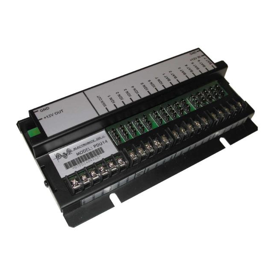
Power Distribution Unit
PDU14-K
Installation/Operations Manual
PDU14
Table of Contents
Applicable Models ............................................ 2
Introduction ....................................................... 2
General Warnings .............................................. 2
Unpacking &Pre-Installation Check ................. 3
Installation & Mounting ................................... 3
Wiring and Setup Instructions ........................... 4
Maintenance ...................................................... 8
Troubleshooting ................................................ 8
Parts List ......................................................... 10
Product Specifications .................................... 11
Warranty .......................................................... 12
PART#: 212-2014-K
1
July 30th, 2019
Advertisement
Table of Contents

Related Manuals for D&R ELECTRONICS PDU14-K


Summary of Contents for D&R ELECTRONICS PDU14-K
-
Page 1: Table Of Contents
Power Distribution Unit PDU14-K Installation/Operations Manual PDU14 Table of Contents Applicable Models ..........2 Introduction ............2 General Warnings ..........2 Unpacking &Pre-Installation Check ....3 Installation & Mounting ........3 Wiring and Setup Instructions ......4 Maintenance ............8 Troubleshooting .......... -
Page 2: Applicable Models
Applicable Models PDU 14 Introduction The Power Distribution Unit (PDU) is a compact and convenient point of load pow- er distribution product for installed electrical devices. By using this device and carefully planning the distribution of mobile equipment power feeds, complex inde- pendent wire runs and unreliable fuse panel connections can be avoided. -
Page 3: Unpacking &Pre-Installation Check
Unpacking & Pre-Installation Check D&R Electronics Co. advises that you open and examine all shipments within 48 hours of receipt. The Power Distribution Unit PDU is shipped pre-assembled and factory tested. All necessary hardware for standard installation is included. Remove all components from the shipping carton. Use this pre-installation check list to verify your unit: 1. -
Page 4: Wiring And Setup Instructions
Wiring and Setup Instructions Warning 1. Looms, grommet, cable ties or other installation hardware should be used to anchor and protect wires 2. All wire should conform to the minimum wire size as specified by the manu- facturer. 3. Splices should be minimized and made in a fashion so as to protect from cor- rosion to reduce loss of conductivity. - Page 5 Figure 2 PDU14 Input and Output Wiring Diagram for the following detailed instructions Wiring information: Red 6 AWG - this is the Battery Input for the PDU Black 6 AWG - this is the Battery return for the PDU Blue 10 AWG - this is the high current output Black 10AWG - this is the high current output return PART#: 212-2014-K July 30th, 2019...
- Page 6 1. Run a 6 AWG wire lead from the Battery via a fusible link or circuit breaker rated at 80A to the PDU14. 2. Cut to length and slide one of the provided grommets over the wire (Figure 3.) 3. Strip 1/2” length of insulation from the end of the wire, insert the bare wire into the pin connector , crimp or solder.
- Page 7 Connecting the ground output (GND) from the PDU This output ground connection is the return path for the device connected to the +12V Power from the PDU. 1. Run the ground wire from device (i.e. light and siren controller) to the PDU mounting location.
- Page 8 Terminal block outputs showing possible fuse combinations 7.5A 7.5A 7.5A 7.5A 7.5A 7.5A 7.5A 7.5A Ignition 7.5A 7.5A 12V Battery 7.5A 7.5A 7.5A 7.5A 7.5A 7.5A 7.5A 7.5A Terminal block outputs showing some possible fuse combinations 12V Bat- Ignition tery Table 2 shows some of the possible combinations when both outputs are used at the same time (Ignition AND 12V Battery).
-
Page 9: Maintenance
Maintenance The PDU14 does not require user maintenance except for the individual fuse replacement. Warning There are no user maintained parts. Do not attempt to open or repair. Contact your local distributor or D&R Electronics for repair Troubleshooting PROBLEM POSSIBLE CAUSE SOLUTION No power at the outputs No power to “12V INPUT”... - Page 10 Parts PART QUAN- DESCRIPTION NOTES NUMBER TITY Standard Parts PDU 14 POWER DISTRIBUTION UNIT 201-0012 PLUG, 75A, RED Power INPUT plug HOUSING 201-0046 PLUG, 75A, Power OUTPUT BLUE plug HOUSING 201-0013 PLUG, 75A, GROUND plugs BLACK HOUSING 196-0002 PIN, 75A, #6 Pins for INPUT and OUTPUT plugs PART#: 212-2014-K...
- Page 11 Specifications General Description No. of Available Connections Power Inputs: 6 AWG +12V 6 AWG Ground 18 AWG Ignition Control Input Power Output 10 AWG @ 20A Max +12V (fused at 30A) 10 AWG Ground Terminal Block Power Outputs Ignition Controlled Power 40A relay (all com- bined output power not exceed 30A max.) Continuous Power the total current not to exceed Ground return path for the Output terminal...
-
Page 12: Warranty
WARRANTY D & R Electronics warrants its new products to be free from defects in material and workmanship, under normal use and service for a period of one year on parts replace- ment. This warranty applies only to original purchasers acquiring the product directly from D&R Electronics, or its authorized dealers.
Need help?
Do you have a question about the PDU14-K and is the answer not in the manual?
Questions and answers