Table of Contents
Advertisement
Quick Links
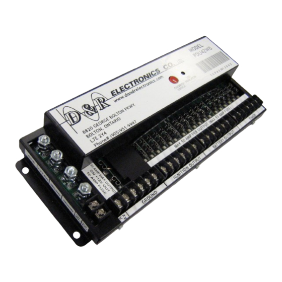
Power Distribution Unit
PDU42WB
Installation / Operations Manual
Table of Contents
Applicable Models ........................................................ 2
Introduction ................................................................... 2
General Warnings .......................................................... 3
Unpacking &Pre-Installation Check ............................. 3
Installation & Mounting ............................................... 4
Wiring and Setup Instructions ....................................... 4
Output Fuse Combinations ............................................ 6
Timed Modes Of Operation ........................................ 12
Maintenance ................................................................ 13
Parts List ..................................................................... 13
Troubleshooting........................................................... 14
Product Specifications ................................................ 15
Warranty ...................................................................... 16
Part NO: 212-0024WB
1
July 30th, 2019
Advertisement
Table of Contents

Related Manuals for D&R ELECTRONICS PDU42WB


Summary of Contents for D&R ELECTRONICS PDU42WB
-
Page 1: Table Of Contents
Power Distribution Unit PDU42WB Installation / Operations Manual Table of Contents Applicable Models ............2 Introduction ..............2 General Warnings ............3 Unpacking &Pre-Installation Check ......3 Installation & Mounting ..........4 Wiring and Setup Instructions ........4 Output Fuse Combinations ..........6 Timed Modes Of Operation ........ -
Page 2: Applicable Models
Each fused output has a red LED to indicate when a circuit fuse is GOOD. The PDU42WB unit provides a single 30A high current output and up to 18 additional outputs divided into “constant/battery”, “ignition controlled” and “timed” outputs to meet the typical in-vehicle equipment installation requirements. -
Page 3: General Warnings
General Warning 1. The use of emergency warning devices does not ensure the safety of the operator. The operator is responsible to ensure safe operation of the vehicle regardless of whether the warning device is in operation or not 2. The effectiveness of this or any warning device is highly dependent on proper installa- tion and maintenance. -
Page 4: Installation & Mounting
Mounting the PDU unit The PDU42WB may be mounted anywhere inside the vehicle away from heat, moisture or the elements. NOTE the PDU is not watertight do not mount it in the engine compartment, on the exterior of the vehicle or an area where moisture/dirt/ other contaminants can fall into the ex- posed areas of the PDU. - Page 5 Figure 1 End View of the PDU42WB showing the location of the Input and Output connectors. The wiring to the PDU will be determined by the installers design of the power distribution and wire routing for the installed equipment.
-
Page 6: Output Fuse Combinations
Output Fuse Combinations PDU42WB Terminal block outputs showing some possible fuse combinations Ignition 12V Battery Outputs on Timer TOTAL ACTUAL LOAD Figure 2 Typical fuse and output combination showing maximum fuse ratings for 10A continuous loads, the chart is read vertically the six possible combinations... - Page 7 1. Run a 6 AWG wire lead from the Battery via a fusible link or circuit breaker rated at 80A to the PDU42WB. 2. Cut the wire to length and strip 1/2” length of insulation from the end of the wire, insert the bare wire into a suitable ring terminal (these are not provided the ring hole must clear a 1/4”...
- Page 8 SPECIAL NOTES: 1. Making a good solid ground connection to the chassis requires the removal of the paint right down to the shiny bare metal at the point of securing the ground wire to the chassis. 2. All ground returns for equipment connected to the PDU should terminate at the PDU using the GROUND terminal block.
- Page 9 necting the ground output (GND) from the PDU This output ground connection is the return path for the device/equipment connected to the +12V OUT from the PDU. 1. Run the ground wire from device (i.e. light and siren controller) to the PDU mounting loca- tion.
- Page 10 Connecting the power output from the PDU Determine the type of power required by the connecting equipment (i.e. ignition controlled, constant/battery or timed) and start connecting the vehicle equipment according to the system design requirements. 1. All power connections will terminate at the PDU, bring the POWER and GROUND (return) wires for the equipment to be connected directly to the PDU.
- Page 11 To set the time delay follow these steps; 1. Locate the Miniature switches at the back of the PDU. 2. Refer to the attached label or Table 1 to determine the switch settings. 3. Use a pen tip or other suitably small tool to set the switches. This will select the time increments to the output off time delay TIME SW-1...
-
Page 12: Timed Modes Of Operation
Timed Modes of Operation Battery Voltage: A) Between 14.0 to 18V the output of the “PDU Timer ” will be ON unconditionally. B) If the battery voltage drops below 14.0V and the ignition is OFF, the “PDU Timer” will commence a predetermined countdown delay at the end of which the unit will shut-off and go into “STANDBY”... -
Page 13: Maintenance
Maintenance The PDU42WB does not require user maintenance except for the individual fuse replacement. Warning There are no user maintained parts. Do not attempt to open or repair. Contact your local distributor or D&R Electronics for repair. The following replacement parts and accessories are available for the PDU 42WB... -
Page 14: Troubleshooting
Troubleshooting PROBLEM POSSIBLE CAUSE SOLUTION No power at any of the out- No power to “12V INPUT” Check 12V INPUT connection for puts loose or missing wires. Check Battery fusible link or circuit No relay “click” breaker, if this is faulty replace it if it is tripped reset it. -
Page 15: Product Specifications
Specifications General No. of Available Connections Description Power Inputs: 6 AWG +12V @ 60A max input current 6 AWG Ground 18 AWG Ignition Control Input Power Output (High Current Connection) 8 AWG @ 30A Max +12V (fused at 50A) 8 AWG Ground Battery Voltage Monitor 18 AWG sense wire @ +12V BATT terminal 18 AWG sense wire @ GND BATT terminal... -
Page 16: Warranty
WARRANTY D & R Electronics warrants its new products to be free from defects in material and workmanship, un- der normal use and service for a period of one year on parts replacement. This warranty applies only to original purchasers acquiring the product directly from D&R Electronics, or its authorized dealers.
Need help?
Do you have a question about the PDU42WB and is the answer not in the manual?
Questions and answers