
Related Manuals for Computherm E280


Summary of Contents for Computherm E280
- Page 1 COMPUTHERM E280 a programmable digital Wi-Fi thermostat for radiator and underfloor heating systems Instruction Manual...
-
Page 3: Table Of Contents
TABLE OF CONTENTS 1. A general description of the thermostat 2. Important warnings and safety recommendations 3. Information appearing on the display of the thermostat 4. Functions accessible in the phone application 5. Location of the thermostat 6. Connection and installation of the thermostat and putting it into operation 6.1. - Page 4 8. Operation-related settings 8.1 Selecting the temperature sensor 8.2. Setting floor temperature limit and corresponding switch sensitivity 8.3 Calibration of the temperature sensor 8.4 Antifreezing 8.5. Memorizing settings in the event of a power failure 8.6 Restoring default setting 9. Basic operation of the thermostat 10. Switching between ON and OFF positions and modes of the device 10.1. Manual mode 1 0.2. Programmed auto mode 10.2.1 Description of the programmed mode 10.2.2. Description of the steps of programming 10.2.3. Modifying temperature until the next switch in the program 11.
-
Page 5: A General Description Of The Thermostat
1. A GENERAL DESCRIPTION OF THE THER- MOSTAT COMPUTHERM E280 Wi-Fi thermostat is a switching device that can be operated by a smartphone or tablet via Internet, and we especially recommend it for controlling heating or cooling systems. It can be easily connected to any gas boiler having a two-wire... -
Page 6: Important Warnings And Safety Recommendations
(see Figure 5), in addition to starting up the boiler. Thus, using several COMPUTHERM E280 type Wi-Fi thermostats, a heating system can be easily divided into zones without a separate zone control system. - Page 7 whose performance does not exceed 0.69 kW (loadability: 230 V AC; 50-60 Hz; 3 A [1 A inductive]). • Before starting to use the thermostat, make sure that the Wi-Fi network is reliably accessible at the place where you intend to use the apparatus.
- Page 8 • Before actually starting to control the device connec- ted to the thermostat, make sure that the device is per- fectly functioning when it is controlled by the thermos- tat and it can be operated reliably. • The software of the thermostat and the telephone applica- tion is constantly upgraded and updated. For proper opera- tion please check regularly whether there is any accessible software or telephone application update, and always use their latest version! Due to constant updates it is possib- le that some functions of the device and the applications operate and appear in a way other than described in these...
-
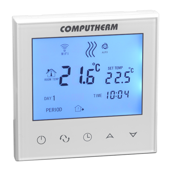
Page 9: Information Appearing On The Display Of The Thermostat
3. INFORMATION APPEARING DISPLAY OF THE THERMOSTAT Figure 1 - 9 -... -
Page 10: Functions Accessible In The Phone Application
4. FUNCTIONS ACCESSIBLE IN THE PHONE APPLICATION Figure 2 - 10 -... -
Page 11: Location Of The Thermostat
6. CONNECTION AND INSTALLATION OF THE THERMOSTAT AND PUTTING IT INTO OPERATION Attention! Make sure that the COMPUTHERM E280 thermo- stat and the apparatus to be controlled are de-energized - 11 -... -
Page 12: Connection Of The Device(S) To Be Controlled
For controlling gas boilers the connection points of the boiler thermostat should be connected to K1 COM-NO (3-4) or K2 (8- 9) connection points of COMPUTHERM E280 (Figure 3). If the device to be controlled has no thermostat connection point, the power supply cable of the device to be controlled should be cut... - Page 13 Within the loadability limits the two parallel operating relays built in the thermostat make simultaneous actuation (open/ close, start/stop) of other electrically operable fittings (e.g. zone valve, pump) possible, in addition to starting up the boiler. Thus, using several COMPUTHERM E280 type Wi-Fi thermostats, - 13 -...
- Page 14 a heating system can be easily divided into zones without a separate zone control system. For example, if you wish to in- stall several thermostats within a heating network, in addition to controlling the boiler the zone control (opening/closing various heating zones) can be ensured without a separate zone control system, by connect- boiler...
-
Page 15: Connecting The Floor Temperature Sensor
For controlling a cooling system If you intend to use the product to control a cooling system then the device to be controlled should be connected to K1 COM- NC (3-5) normally-closed connection points located on the rear side of the product. For possible use of the connection points of the relay marked by K2 (8-9) take into consideration that they will always switch oppositely to K1 COM-NC (3-5) connection points. -
Page 16: Connection To The Electrical Network
maximum temperature, and the thermostat switches off the out- puts whenever this temperature is reached. This function may be especially useful, for safety reasons, for underfloor and electrical heating systems. If you wish to use the sensor to measure floor temperature, we propose to put the temperature sensor in a short copper pipe and sink it into the floor so that it can be replaced easily when a breakdown occurs. -
Page 17: Mounting The Thermostat
and L of the terminal block located on the rear side of the thermos- tat. You do not have to take care of phase correctness during the connection process (Figure 3). 6.4. Mounting the thermostat To install the thermostat you should separate the front plate from the black plate. -
Page 18: Installing The Application
6.5. Installing the application The thermostat can be controlled by both a smartphone and a tablet with the help of free application COMPUTHERM E Series. Application COMPUTHERM E Series can be downloaded to iOS and Android operating systems. The applications are acces- sible through the following link or using a QR code: http://quantrax.hu/computherm-wi-fi-termosztatok/... -
Page 19: Connecting The Thermostat To A User Account
6.7. Connecting the thermostat to a user account • You can search for COMPUTHERM E280 thermostats connected to the Wi-Fi network concerned by tapping the “Search” icon in the left bottom corner (i.e. this requires that the thermostat is connected to the same Wi-Fi network used for the phone). -
Page 20: Controlling The Thermostat By Multiple Users
• Connect your smartphone/tablet to the Wi-Fi network to which the COMPUTHERM E280 thermostat has been con- nected. • On the apparatus you want to use for controlling download then start application COMPUTHERM E Series. -
Page 21: Basic Settings
(PV) and set (SV) temperatures. Attention! If you want to avoid that other users can add your COMPUTHERM E280 thermostat to their phone app- lications, you can disable this operation as described in Sub-chapter 7.2. -
Page 22: Disabling Further Connections Of The Thermostat Assigned To The Application
Wi-Fi network. Attention! When a phone/tablet has already been connected to the Wi-Fi network concerned and application COMPUTHERM E Series has been opened on it then addition of the ther- mostat to this phone/tablet cannot be disabled with function “Lock current thermostat”... -
Page 23: Setting The Day And Time
mostat from the application by tapping the “Delete current thermostat” icon. 7.4. Setting the day and time • Using phone application: To set date and time click on the icon in the phone app- lication after the thermostat has been selected. Now the thermostat sets date and time automatically via Internet. •... -
Page 24: Locking Operating Buttons
With the help of the buttons set the day. By tapping the button again the thermostat will be reset to its initial state. 7.5. Locking operating buttons • Using phone application: To lock operating buttons tap the icon in the phone app- lication after the thermostat has been selected. Hencefor- ward the device cannot be controlled by the touch buttons on the thermostat until the operating buttons are unlocked. -
Page 25: Operation-Related Settings
8. OPERATION - RELATED SETTINGS For the operation of the thermostat some functions can be set. Operation-related settings can be performed in the following way: • Using phone application: Tap the icon in the right bottom corner for 1 second. The following screen appears: where you can select the function to be modified. - Page 26 button for a short time. - Now you enter the settings menu: in the left bottom cor- ner “SEN” appears and the set temperature will be repla- ced by numbers 00. - Tapping the button you can switch between the func- tions to be set.
- Page 27 Detailed Display Function Setting Options Default Setting Description Internal sensor Floor temperature Selecting the temperature Chapter 8.1 sensor sensor Internal and floor temperature sensors Setting the floor temperature Chapter 8.2 5 – 99 °C 42 °C sensor limit Selecting switch sensitivity for Chapter 8.2 1 –...
-
Page 28: Selecting The Temperature Sensor
8.1. Selecting the temperature sensor Attention! This function is only available if the floor them- perature sensor is connected to the thermostat. During the use of the thermostat the temperature sensor you want to use can be chosen. In the base case the thermostat displays the measured temperature on the basis of the built-in temperature sensor and switches the set output(s) according to the set temperature. -
Page 29: Setting Floor Temperature Limit And Corresponding Switch Sensitivity
If you have connected also a floor temperature sensor to your thermostat and you have chosen the sensor of the thermostat so that the main sensor is the built-in temperature sensor, and you use the floor temperature sensor as a safety sensor (2 / In-s control, Out-s limit) then you can check the temperature measured by the floor temperature sensor in the application at the place shown in Figure 2. -
Page 30: Calibration Of The Temperature Sensor
below the set temperature, considering the switch sensitivity set for the floor temperature (DIF). This means that when the OSV value is set to 42°C and the DIF value to 2°C, the outputs of the thermostat will be disabled when the temperature mea- sured by the floor temperature sensor reaches 44°C, and the outputs will resume normal operation only after the temperature measured by the floor temperature sensor goes below 40°C. -
Page 31: Restoring Default Setting
you can select the mode in which the thermostat continues to operate: • 00/OFF: the thermostat turns off and remains turned off until this mode is altered, regardless whether the thermostat was on or off before the power failure. 01/ON: the thermostat returns to the same state in which it •... -
Page 32: Basic Operation Of The Thermostat
value (08) then the device will not return to default setting but save the settings and exits the operation-related settings menu. 9. BASIC OPERATION OF THE THERMOSTAT When it is switched on, on the basis of the temperature measured by itself and currently set (manually or through programming), the ther- mostat controls the apparatus(es) (e.g. -
Page 33: Switching Between On And Off Positions And Modes Of The Device
mostat is off (i.e. they will not actuate the apparatuses connec- ted to the thermostat). 10. SWITCHING BETWEEN ON AND OFF POSI- TIONS AND MODES OF THE DEVICE The thermostat has the following 2 positions: • Off position • On position You can switch between off and on positions in the following way: •... -
Page 34: Manual Mode
When the thermostat is on, it possesses the following 2 modes of operation: • Manual mode • Programmed auto mode You can switch between the modes in the following way: • Using phone application: by touching icons • On the thermostat: touching the button The currently selected mode is indicated as follows: •... -
Page 35: 0.2. Programmed Auto Mode
on the thermostat, the output of the thermostat will switch off. The temperature to be maintained by the thermostat can be specified in 0.5°C steps (the minimum and maximum values of the adjustable range are 5°C and 99°C, respectively). The currently set temperature can be modified in the following way: •... -
Page 36: Description Of The Steps Of Programming
programmed auto mode the thermostat operates automatically, and cyclically repeats the entered switches every 7 days. The following 3 options are available to program the thermostat: • 5+2 mode: setting 6 switches per day for 5 working days and 2 switches per day for 2 days of the weekend •... - Page 37 is located at the top of the screen for programming, beside the legend LOOP. Touching this, you can switch between programming modes as follows: - 12345,67: 5+2 mode - 123456,7: 6+1 mode - 1234567: 7+0 mode c) Switches belonging to a given programming mode are below the indication of the programming mode.
- Page 38 b) With the buttons choose the preferred programming mode as follows: - for 5+2 mode: 12345 - for 6+1 mode: 123456 - for 7+0 mode: 1234567 Now touch the button again. c) Following this, you can specify or modify various switch times and temperatures as follows: - You can switch between switch times with the button.
-
Page 39: Modifying Temperature Until The Next Switch In The Program
succeed each other during the course of the day, i.e. you should specify switches in chronological order. 10.2.3. Modifying temperature until the next switch in the program: When the thermostat is in programmed automatic mode but you want to modify the set temperature temporarily until the next switch in the program, you can do this in the following way: • Using phone application: with the icons or mo- ving the slide (groove) on the circular scale •... - Page 40 fails to respond to modifications then the connection between the product and the Internet-based interface has broken. That can be due to several reasons. The problem is most probably caused by the Wi-Fi router being used. It is expedient to restart routers from time to time, by switching off and on the power supply.
- Page 41 - 41 -...
-
Page 42: Technical Data
12. TECHNICAL DATA • Trademark: COMPUTHERM • Model identifier: E280 • Temperature control class: Class I • Contribution to the efficiency of seasonal space heating: 1 % • Temperature measuring range (floor and internal temperature sensors): 0 °C – 50 °C (in 5 °C steps) •... - Page 43 • Standby power consumption: 0.5 W • Dimensions: 86 x 86 x (17 + 33) mm • Mass: thermostat: 175 g + floor temperature sensor: 60 g - 43 -...
- Page 44 The COMPUTHERM E280 type Wi-Fi thermostat complies with Directives RED 2014/53/EU and RoHS 2011/65/EU QUANTRAX Kft. Manufacturer: H-6726 Szeged, Fülemüle u. 34. Telephone: +36 62 424 133 • Fax: +36 62 424 672 E-mail: iroda@quantrax.hu Web: www.quantrax.hu • www.computherm-hungary.hu Country of origin: China...
Need help?
Do you have a question about the E280 and is the answer not in the manual?
Questions and answers