Advertisement
Quick Links
AGM Pin Welder
Instruction Manual
Model JS-1
AGM Industries, Inc.
16 Jonathan Drive, Brockton, MA 02301
TELEPHONE: 1 (800) 225-9990 FAX: 1 (800) 342-5246
www.agmind.com
Read equipment manufacturer's manual before using this product. Failure
to do so can result in serious injury or death.
Advertisement

Subscribe to Our Youtube Channel
Related Manuals for AGM JS-1


Summary of Contents for AGM JS-1
- Page 1 AGM Pin Welder Instruction Manual Model JS-1 AGM Industries, Inc. 16 Jonathan Drive, Brockton, MA 02301 TELEPHONE: 1 (800) 225-9990 FAX: 1 (800) 342-5246 www.agmind.com Read equipment manufacturer’s manual before using this product. Failure to do so can result in serious injury or death.
- Page 2 As is true for all types of welding equipment, serious injury may result if not properly used and maintained. Though numerous safety features are built into this welder, the users must familiarize themselves with the proper installation, usage and maintenance of the welder as outlined in this instruction manual.
- Page 3 TABLE OF CONTENTS – MODEL JS-1 WELDER PAGE Foreword and Warranty Description of Welding System System Operating Instructions Model 250-C Weld Gun Description of Accessories Installing and Removing Collets, Stops, etc. Installing 437G- & 250C-G Type Stops 250C-G & 437-G Type Stops Selection Sheet...
- Page 4 FOREWORD The AGM Model JS-1 is the most up to date welding system in the pin and stud welding industry. This welding system has been carefully constructed from the finest and most reliable parts available, with all components being rigidly inspected and tested to assure long and trouble free performance.
- Page 5 The weld gun has a contoured, pistol shaped handle with a trigger button. As a safety feature, all AGM welding systems are designed so that the stud or pin must be in contact with the work piece before the weld cycle can be actuated.
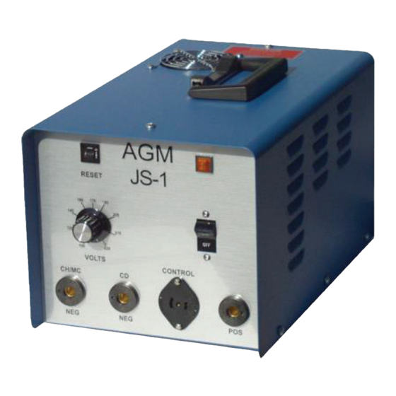
- Page 6 DESCRIPTION OF WELDING SYSTEM SYSTEM SPECIFICATIONS Model JS-1 Power Pack Model 250C Weld Gun Construction 16 Ga. Fabricated Steel Type Pistol Grip Mode Contact 13 ½” L Dimensions 9 “W Weight 2 lbs. 8” H 8 ½” L x 2” D Dim.
- Page 7 WELDING OPERATION WELDER SET UP Set up the weld gun as described on pages 8-15 (refer to the Gun Set-Up sheets for specific details). Next, install the cables as shown below. Note that the illustration shows the gun set up for “reverse” polarity (ground to “negative”). This polarity is used for welding tipped CD pins or studs to galvanized steel.
- Page 8 WELDING OPERATION Adjust the voltage control to the desired setting for your application. Turn the AC line switch “on”. The Amber Weld Ready Light will glow within three seconds, indicating that the weld capacitors are charged and the unit is ready to weld.
- Page 9 MODEL 250-C WELD GUN The AGM Model 250-C weld gun is a semi-automatic, contact welding tool that has been carefully engineered and designed for use with a wide variety of AGM accessories. Given normal care and use, this weld gun will require very little maintenance. When repairs are required, the complete disassembly of the weld gun can be accomplished in a matter of minutes.
- Page 10 ADAPTOR RING – This is used to extend the three legs in certain applications, such as when a longer collet protector is used to weld aluminum pins. ADJUSTABLE FOOT ASSEMBLY – This is necessary when welding very long CD pins and studs. It is used in conjunction with a stop and spark shield to stabilize the pin or stud.
- Page 11 MODEL 250-C WELD GUN INSTALLATION AND REMOVAL PROCEDURES INSTALLING COLLET AND COLLET PROTECTOR A. Examine the inside of the collet adaptor assembly for pitted areas or splatter. Clean by scraping with sharp object or replace if necessary. B. Insert the collet into the collet adaptor assembly, making sure that it seats against the inside shoulder.
- Page 12 MODEL 250-C WELD GUN INSTALLING TYPE 437G STOP A. Place stop inside the rear of the collet. B. Insert the collet, with stop, into the collet adaptor assembly. C. Locate and tighten the collet holding set screws, as previously described. D.
- Page 13 250C-G TYPE STOPS STUD LENGTH CATALOG NUMBER STOP LENGTH ¼” - 5/16” 7” 250C-G-*-0250 3/8” – 7/16” 6.875” -0375 ½” – 9/16” 6.750” -0500 5/8” 6.625” -0625 ¾” 6.500” -0750 7/8” 6.375” -0875 1” 6.250” -1000 6.000” 1-1/4” -1250 1-1/2” -1500 5.750”...
- Page 14 MODEL 250-C WELD GUN INSTALLATION OF COLLET ADAPTOR ASSEMBLY This procedure can be accomplished with a collet and stop or collet protector already installed. A. Before installing, be sure that the tapered surfaces of the collet adaptor and shaft assembly are clean. Wipe with a clean cloth if necessary. B.
- Page 15 MODEL 250-C WELD GUN INSTALLING OR CHANGING SPRING A. Unscrew the end cap from the gun housing. B. Unscrew stop nut from the end of gun shaft. C. Unscrew the spring retainer and remove the washer from the housing. D. Remove the spring from the shaft. E.
- Page 16 MODEL 250C WELD GUN DISASSEMBLY OF THE WELD GUN (Refer to Illustration No. 1 page 17) A. Remove handle cover screws (items 28, 29, & 45). B. Lift off the handle cover (item 38). C. Remove the nut, washer, and cap screw (items 34, 35, & 36) from the welding lead (item 40).
- Page 17 ILLUSTRATION NO. 1 (Not Shown) 2615-M ADAPTER ASSEMBLY INCLUDES ITEMS # 25,13,14 &24...
- Page 18 Leave weld cables coiled up while welding. Use wrong ground polarity for the application. Use pins or studs not designed for use with the AGM JS-1 Welding System. Care must be taken to operate this welder on the rated AC line voltage range (95-130 VAC) only.
- Page 19 PREVENTATIVE MAINTENANCE (see note bottom of page) The Model JS-1 welding system has been designed to give maximum service with little maintenance. Like most equipment, however, a small amount of care and preventative maintenance is a wise investment. To minimize down time when repairs are required, AGM recommends you always have a spare gun and cables available and in good working order.
- Page 20 SET-UP FOR WELDING STEEL/STAINLESS STEEL WELD PINS GUN SET-UP WITH HEAVY (3”) SPRING 1. 12 & 10 gauge pins to galvanized steel 26 Gauge (.0217) or thicker. A. Set up the gun as described on page 8-15 of this manual. Refer to the chart below for collet and collet protector part numbers.
- Page 21 SET-UP FOR WELDING ALUMINUM WELD PINS OVER 1” GUN SET UP WITH HEAVY 3” SPRING & 2367-M ADAPTOR ASSEMBLY A. If previously installed, remove the legs (2) from gun. B. Install proper collet (5) and protector (4) make sure collet holding set screws are tightened securely.
- Page 22 SET-UP FOR WELDING PINS OVER 7” LONG GUN SET-UP WITH HEAVY 3” SPRING & 2318-M FOOT PIECE ASSEMBLY A. Install proper collet (2), stop (1) and protector (3). Make sure collet holding setscrews are tightened securely. See page 22 or 23 for part numbers. B.
- Page 23 SET-UP FOR WELDING FLANGED STEEL & STAINLESS STEEL STUDS UP TO AND INCLUDING ¼-20 DIAMETER UP TO 7” LONG GUN SET-UP WITH HEAVY 3” SPRING A. Set up the gun as described on pages 8-15 of this manual, using the proper collet and collet protector.
- Page 24 SET-UP FOR WELDING TO CURVED SURFACES GUN SET-UP A. Set up the gun as described on pages 8-15 of this manual, using the proper collet and collet protector or stop (if required). Tighten the collet holding setscrews securely. B. Install the 1628-M leg support ring (2) over the three 1151-M legs (1). The metal inserts should face down toward the legs.
- Page 25 TYPICAL TEMPLATE SPECIFICATIONS Material: Phenolic sheet Thickness: .0125” min., .0250” max The above drawing shows the spacing and diameter of the leg location holes. The two standard 1151-M legs are inserted into these holes. To ensure that the welded stud is perpendicular to the work surface, a third leg, shortened by an amount equal to the template thickness, may be used in the weld gun.
- Page 26 SET-UP FOR WELDING THROUGH A TEMPLATE GUN SET UP A. Make a template as described on page 25. B. Set up the gun as described on pages 8-15 of this manual, using the proper collet and collet protector or stop (if required). Be sure the collet holding set screws are tightened securely.
- Page 27 SET-UP FOR WELDING FLANGED & NON-FLANGED ALUMINUM & NON- FLANGED STEEL / STAINLESS STEEL STUDS THROUGH ¼-20 DIAMETER GUN SET-UP WITH HEAVY 3” SPRING A. Set up the gun as described on page 8-15 of this manual, using the proper collet and stop.
- Page 28 ALTERNATE GUN SET-UP FOR STUDS OVER 1-3/8” LONG GUN SET-UP WITH HEAVY 3” SPRING & 2318-M FOOT PIECE ASSEMBLY A. Install proper stop (1), collet (2) and protector (3). Make sure the collet holding set screws are tightened securely. See the chart below and on previous page for part numbers.
- Page 29 SET-UP FOR WELDING CUPPED PINS IN THE FIELD GUN-SET UP WITH MEDIUM 2” SPRING A. If previously installed, remove the three 1151-M legs, as they will interfere with the proper gun shaft movement. B. Install the 2506-M-200 medium spring as instructed on page 15 of this manual. B1.Install the weld lead of the gun lead extension into the weld receptacle labeled THIS SET-UP IS FOR WELDING TO 22 GA.
- Page 30 AGM insulated cupped pins are furnished with an insulator disc adhered to the underside of the washer. Be sure to specify “insulated”...
- Page 31 437-PM MAGNETIC COLLET INSTRUCTIONS FOR REPLACEMENT OF WORN OUT COLLET PARTS The 437-PM-RK Repair Kit should be used to rebuild the 437-PM Magnetic Collet. It includes the following: 437-PM-1 Collet Insert, 437-PM-2 Cap Screw, 437-PM-7 Insulator Disc, 437-PM-4 Screw Sleeve Insulator, as well as the proper size Allen Wrench.
- Page 32 WIRING DIAGRAM JS-1...
- Page 33 WIRING DIAGRAM LEGEND – MODEL JS-1 SYMBOL PART NUMBER DESCRIPTION 3087-E Capacitor, Welding 2475-E Line Switch/Circuit Breaker CB1-A&B Part of 2475-E Switch only “ “ “ CB1-C SCR Voltage Sensor 3081-E -15 Circuit Breaker, 15 Amp 2267-E Capacitor 3074-E Relay, Discharge...
- Page 34 Illustration No. 2...
- Page 35 Illustration No. 3...
- Page 36 Illustration No. 4...
- Page 37 JS-1 POWER PACK PARTS LIST PART NO. QUANTITY DESCRIPTION 1046-E Receptacle, Weld 1062-E Resistor, Discharge 1086-M Name Plate 1097-E Line Cord 1107-E Receptacle, AC Control 1142-E Ground Cable, Standard 1279-E Gun Lead Extension 2079-M-0375 Screw, Cover 2394-M-JS1 Weld Set Up Chart...
- Page 38 NOTES Welder Serial Number ________________ Gun Serial Number ________________ AGM Industries, Inc. 16 Jonathan Drive, Brockton, MA 02301 Telephone: 1 (800) 225-9990 FAX: 1 (800) 342-5246...
Need help?
Do you have a question about the JS-1 and is the answer not in the manual?
Questions and answers