Table of Contents
Advertisement
Quick Links
LED FLASHER AND TRAFFIC DIRECTOR POSITIVE CONTROL
Content
Basic information
Flash pattern
Technical specification
Installation instruction
Wiring Diagram
Maintenance
Troubleshooting
Warranty and product return policy
Wiring diagram
PART#: 212-0047
FPC8TL-PIC
Installation/Operations Manual
page
2
2
2
3
5
8
8
9
Separate page
October 18, 2019
Advertisement
Table of Contents

Summary of Contents for D&R ELECTRONICS FPC8TL-PIC
- Page 1 LED FLASHER AND TRAFFIC DIRECTOR POSITIVE CONTROL FPC8TL-PIC Installation/Operations Manual Content page Basic information Flash pattern Technical specification Installation instruction Wiring Diagram Maintenance Troubleshooting Warranty and product return policy Wiring diagram Separate page PART#: 212-0047 October 18, 2019...
-
Page 2: Basic Information
Basic information The FPC8TL-PIC Flasher is general purpose positive control flasher. It can be use for any low power consumption LED flashing. Generally it is use in Tailgate LED light flashing, mini-tech lightbar, PL22B , SL24. It can be use for single or multiple function depend on application. -
Page 3: General Warning
General Warning 1. The use of emergency warning devices does not ensure the safety of the operator. The operator is responsible to ensure safe operation of the vehicle regardless of whether the warning device is in operation or not 2. The effectiveness of this or any warning device is highly dependent on proper in- stallation and maintenance. - Page 4 Mounting Step 1: Determine an appropriate mounting location. Step2: Confirm there is adequate access and clearance for the wiring and its connections. Step3: Secure the FPC8 TL with 2 self tapping mounting screws (not supplied). NOTE: The FPC8 TL may be mounted anywhere inside the vehicle, inside the warning device or any convenient location that is determined by proper planning and installation techniques.
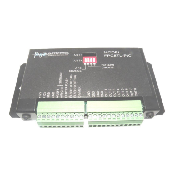
- Page 5 Figure 1 Wiring diagram of the FPC8TL showing the location of the Input/output pins PART#: 212-0047 October 18, 2019...
-
Page 6: Wiring Information
Wiring information: Connector 1: 1 +12 V BATTERY 2 +12 V BATTERY 3 GROUND BATTERY 4 GROUND BATTERY 5 INPUT 1 (ACTIVATE LEFT AROW) +12V ACTIVATE 6 INPUT 2 (ACTIVATE RIGHT ARROW) +12V ACTIVATE 7 INPUT 3 (ACTIVATE CENTER FLASH) +12V ACTIVATE 8 INPUT 4 (ACTIVATE OUT1 &... -
Page 7: Maintenance
Port 6 - Input 2: Triggering switch (+12V to activate Right Arrow) Port 5 and 6 - Activating both port together (+12V to activate Center Out) Port7 - Input 3: Triggering switch (+12V to activate Center arrow) Port 8 - Input 4: Triggering switch (+12V to activate flash for output 1 and output 8) Port 9 - Input 5: Triggering switch (+12V to activate flashing for output 1 to output 8) -
Page 8: Warranty
WARRANTY D&R Electronics warrants its new products to be free from defects in material and workman- ship, under normal use and service, for a period of one year on parts replacement, and one year on labour. This warranty applies only to original purchasers acquiring the product directly from D&R Electronics, or its authorized dealers.