Table of Contents
Advertisement
Quick Links
Advertisement
Table of Contents

Related Manuals for Electro-Voice Telex RE-1


Summary of Contents for Electro-Voice Telex RE-1
- Page 1 Op er ating In struc tions RE-1 User Guide...
-
Page 2: Table Of Contents
Quick Set-Up ................. . 1-1 Quick Set-up: Re ceiver . -
Page 3: Quick Set-Up
Quick Set-up: Receiver 1. Do not connect the receiver to any other equip ment yet! 2. Connect the two an tennas to the receiver. 3. Plug the power supply into the back of the re ceiver and into an out let 4. - Page 4 1-2/Blank...
-
Page 5: Sys Tem De Scrip Tion
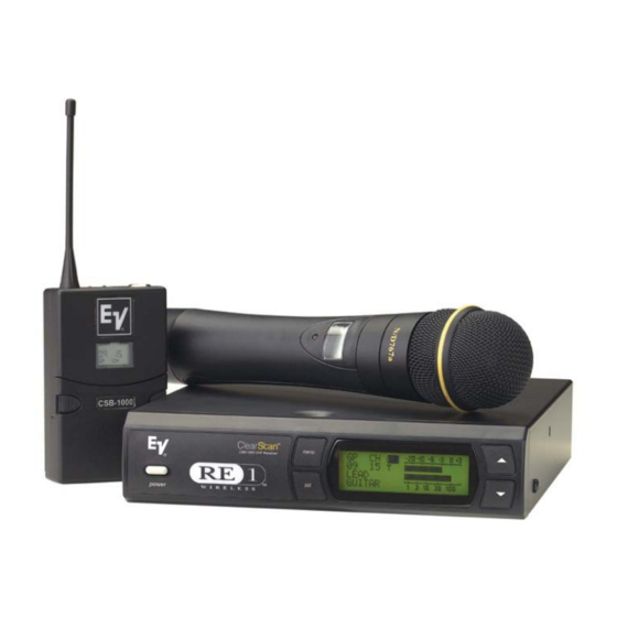
The CSR-1000 Wire less Mi cro phone sys tem com bines fre- quency agility and ease of use like no other. The CSR-1000 transmitters and re ceivers operate over a 24 MHz bandwidth in the UHF por tion of the spectrum. Sys tem Fea tures In clude: Ad vanced ClearScan •... - Page 6 2-2/Blank...
-
Page 7: Detailed Compo Nent De Scrip Tions
CSR-1000 Receiver CSR-1000 Re ceiver Con trols, Con nec tors and In di ca tors power Antenna Made in U.S.A. Program 1. Power ON/OFF 2. Graph i cal Dis play Chan nel Dis play Bat tery Strength In di ca tor Di ver sity In di ca tor RF Strength of Signal Indicator Au dio Level In di ca tor... -
Page 8: Re Ceiver Setup And Op Er A Tion
Re ceiver Setup and Op er a tion 1. Place the re ceiver and an tennas where there is a clear line of sight to the area where the transmitter will be used. Ro - tate the an tennas to separate them by 90 de grees. 2. - Page 9 6. Change Lock-Out. By pressing and holding the UP and DOWN ar row keys to gether for 3 seconds, the SET key is disabled. The MENU button still al lows dif ferent screens to be displayed but no settings can be changed and ClearScan will not run.
- Page 10 Handheld Trans mit ter CSH-1000 7 5 5 0 5 0 (ON OPPOSITE SIDE) Fig ure 3 Handheld Trans mit ter CSH-1000 Con trols, Con nec tors and In di ca tors 10. Battery Cover - Screw type 11. Transmit RF Power Switch Mi cro phone Head - In ter change able Main Display - LCD (Channel, Fre quency or Bat tery Level Indication) Low Battery LED - Lights when battery is low...
- Page 11 Handheld Trans mit ter Setup and Operation 1. Insert Bat tery. Re move the battery com partment cover by unscrewing it com pletely. Insert a 9V bat tery, terminal end first into the battery compartment. NOTE: The CSH-1000 unique design allows the battery to be inserted and used re gardless of the pos itive and negative ter- mi nal po si tion.
-
Page 12: Bodypack Trans Mit Ter
Bodypack Trans mit ter 7 5 5 0 5 0 CSB-1000 Fig ure 5 Bodypack Trans mit ter CSH-1000 Con trols, Con nec tors, and In di ca tors Antenna - flexible 1/4 wave an tenna re movable (re placement part see Section 8) Power On/Off Switch Low Bat tery LED In di ca tor TA4 Au dio Connector... - Page 13 Bodypack Trans mit ter Setup and Op er a tion 1. In stall An tenna. The CSB-1000 is equipped with a de - tachable an tenna. Screw in the an tenna in cluded with the system. See the ac cessories sec tion at the end of this man - ual for in formation on op tional antennas for the CSB-1000.
- Page 14 Trans mit ter Dis play Squence: Battery Gauge: Display 3 seconds Group Channel Press MENU Frequency Display Press MENU Battery Gauge Press MENU Bat tery In di ca tor: Battery condition is displayed on power up. The low battery LED should flash once to indicate an ac ceptable bat tery. If the battery is nearly depleated, the low bat tery LED will come on and stay on.
-
Page 15: Receiver Dis Play Screens And Functions
Main Op er ating Screen Display: 1. Group Num ber 2. Chan nel Num ber · · · · · · · · · · · · · · · · 01 to 16 3. Mi cro phone La bel or Name · · · · · · · 2 lines x 9 characters - all cap itals 4. -
Page 16: Group / Chan Nel Edit Screen
Group / Chan nel Edit Screen Dis play: 1. Fre quency Band Des ig na tion · · · · · · A or B 2. Group Num ber· · · · · · · · · · · · · · · · · · 10 fac tory + 10 user de fined 3. -
Page 17: Frequency Edit (User Groups Only)
Frequency Edit (User Groups Only) Dis play: 1. Fre quency Band Des ig na tion · · · · · · A or B 2. Group Num ber· · · · · · · · · · · · · · · · · · 10 fac tory + 10 user de fined 3. -
Page 18: Func Tions Screen
Func tions Screen Con trols: Use [UP] [DOWN] to select and view other func tions Use [SET] to start the function ClearScan ClearScan All searches all de fined fre quency groups for the ones with the great est num ber of re ceiver channels clear of in - terference. -
Page 19: Clearscan Tm Current Groups
ClearScan Cur rent Group ClearScan Current Group scans channels within the cur - rently se lected frequency group and displays the chan nels that are clear of in terference. Press [SET] to initiate Press [MENU] to abort After scanning the cur rently se lected group, ClearScan display the chan nels that are free of in terference. -
Page 20: Edit Microphone Label / Name
Edit Mi cro phone La bel/Name Dis play: 1. Mi cro phone La bel/Name 2. Char ac ter Set Con trols: 1. [MENU] goes to next screen. 2. [SET] (First time) enters Edit Mode: Starts flash ing first char acter in Name/La bel Flashes first char acter of the Name/La bel in the Char ac ter Set 3. -
Page 21: Copy Group
Copy Group Selecting the Copy Group will copy the currently se lected group to the first un used User Group. Press [SET] to accept the group and place the unit into the Frequency Edit Screen (User De fined groups only) for ed iting. Press [UP/DOWN} to select a different user group. - Page 22 4-8/Blank...
-
Page 23: Guide Lines And Rec Om Men Da Tions For Best Performance
Com pat i bil ity The transmitter and receiver must be of the same fre quency band and set to the same group and channel in or der to work to gether. The CSR-1000 is available in two fre quency bands, A and B. - Page 24 5-2/Blank...
-
Page 25: Trou Ble Shoot Ing Guide
Prob lem No au dio and no display on the re ceiver No au dio and no RF signal indicator on the receiver display No Au dio with good RF signal indica- tor but no (or low) Au dio indicator on the re ceiver dis play No (or low) Au dio with good RF sig- nal and Au dio indicators on receiver... - Page 26 Prob lem Interference (continued) Short range or drop-outs Can't change settings on re ceiver or transmitter Can't change fre quency setting for a channel Bodypack or Handheld transmitter will not turn off, display says On-Loc Trou ble Shoot ing Guide (con tin ued) Pos si ble Causes Receiver is too close to digital sig nal pro ces sor or sim i lar de vice...
-
Page 27: Technical Specifications
ection Technical Specifications CSR-1000 Receiver Spec i fi ca tions Over all Re ceiver Type..........Syn the sized PLL Frequency Range (RF) . - Page 28 Mi cro phone Head RC767A....ElectroVoice N/D 767a cardioid N/DYM dynamic Mi cro phone Head RC510 ..... . . ElectroVoice RE 510 cardioid con denser Stan dard Lavalier Mi cro phone .
- Page 29 FCC IN FOR MA TION The TELEX Re ceiver CSR-1000 is au thorized un der Part 15 of the Fed eral Com munica- tion Com mis sion. The Telex CSB-1000 and CSH-1000 Transmitters are type Ac cepted un der United States Fed eral Com mu ni ca tions Com mis sion Part 74.
- Page 30 7-4/Blank...
-
Page 31: Ac Ces Sories And Parts
1/4 Wave Rx An tenna (A/B) 1/4 Wave Rx An tenna (D/E) 1/2 Wave Rx An tenna (A) 1/2 Wave Rx An tenna (B) 1/2 Wave Rx Antenna (D + E) 1/2 Wave An tenna Bracket Antenna/Power Dis tribution (A, B, D, E) Ter mi na tion Plug for APD4 Di rec tional Rx An tenna (A, B, D, E) Co ax ial An tenna Ca ble... - Page 32 8-2/Blank...
-
Page 33: Cus Tomer Ser Vice In For Ma Tion
Fur ther Telex re serves the right to ship new and/or im proved prod ucts which are sim ilar to the form, fit and func tion of prod ucts orig inally or dered. For other office lo cations see www.electrovoice.com Eu rope... - Page 34 9-2/Blank...
-
Page 35: Limited Warranty
TELEX Communications, Inc. (”Telex”) war rants to the user, who orig inally pur chased the serialized product de livered with this card, that the product will be free from de fects in material and workman- ship for the fol lowing pe riods af ter such date of pur chase. Ma terial 36 months, work manship 36 months. - Page 36 10-2/Blank...
- Page 37 • TELEX COM MU NI CA TIONS, INC. 12000 Port land Ave. South, Burnsville, MN 55337. PN 803333 Rev A June 2004 Made in U.S.A.