
Related Manuals for Hoshizaki KMD-530MRJZ


Summary of Contents for Hoshizaki KMD-530MRJZ
- Page 1 Instruction Manual Modular Crescent Cuber Models KMD-530MRJZ hoshizakiamerica.com Issued: 8-13-2021...
- Page 2 Should the reader have any questions or concerns which have not been satisfactorily addressed, please call, send an e-mail message, or write to the Hoshizaki Technical Support Department for assistance. Phone: 1-800-233-1940; (770) 487-2331 Fax: 1-800-843-1056;...
-
Page 3: Table Of Contents
1. Air-Cooled Models (MAJ) ..................7 2. Water-Cooled Models (MWJ) ................... 8 3. Remote-Cooled Models (MRJZ) ................9 4. Remote Condenser Unit URC-5FZ (use with KMD-530MRJZ) ......10 II. Installation and Operating Instructions ................11 A. Location ........................11 B. Checks Before Installation ....................11 C. -
Page 4: Important Safety Information
Important Safety Information Throughout this manual, notices appear to bring your attention to situations which could result in death, serious injury, damage to the appliance, or damage to property. WARNING Indicates a hazardous situation which could result in death or serious injury. - Page 5 WARNING, continued • Children should be properly supervised around the appliance. • Do not climb, stand, or hang on the appliance or allow children or animals to do so. Serious injury could occur or the appliance could be damaged. • Do not use combustible spray or place volatile or flammable substances near the appliance.
-
Page 6: Specifications
HI-467PSI LO-230PSI HI-427PSI LO-230PSI Refrigerant 404A 1 LB. 5 OZ. 404A 14.1 OZ. 2. KMD-530M_J(Z) Single Phase Model Number KMD-530MAJ KMD-530MWJ KMD-530MRJZ AC Supply Voltage 115/60/1 115/60/1 115/60/1 Compressor 115V 10.5RLA 70LRA 115V 9.35RLA 70LRA 115V 9.73RLA 70LRA Pump 120V 0.5FLA 23W 120V 0.5FLA 23W... -
Page 7: Dimensions/Connections
B. Dimensions/Connections Units: mm [in.] 1. Air-Cooled Models (MAJ) Rear Side ELECTRICAL SUPPLY OPENING 22 [7/8] DIA ICEMAKER WATER INLET 1/2” FPT M5 MOUNTING HOLES ICEMAKER DRAIN OUTLET 3/4” FPT [2-5/8] [2-7/8] [3-1/8] [3-1/8] [22-7/8] [24-1/8] Bottom KMD-460MAJ KMD-530MAJ [9-3/8] [13] [1-1/2] A 768 [30-1/4]... -
Page 8: Water-Cooled Models (Mwj)
2. Water-Cooled Models (MWJ) Units: mm [in.] Rear Side ELECTRICAL SUPPLY OPENING 22 [7/8] DIA ICEMAKER WATER INLET 1/2” FPT CONDENSER WATER INLET 1/2” FPT CONDENSER WATER OUTLET 3/8” FPT M5 MOUNTING HOLES ICEMAKER DRAIN OUTLET 3/4” FPT [3/8] [2-5/8] [2-7/8] [3-1/8] [3-1/8]... -
Page 9: Remote-Cooled Models (Mrjz)
3. Remote-Cooled Models (MRJZ) Side Rear Bottom KMD-530MRJZ A 768 [30-1/4] B 761 [30] C 498 [19-5/8] D 103 [4] E 202 [8] F 173 [6-3/4] G 117 [4-5/8] H 55 [2-1/8] 278 [11] J 133 [5-1/4] K 56 [2-1/4]... -
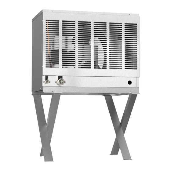
Page 10: Remote Condenser Unit Urc-5Fz (Use With Kmd-530Mrjz)
4. Remote Condenser Unit URC-5FZ (use with KMD-530MRJZ) Units: mm [in.] Rear NOTICE Allow 24" (61 cm) clearance at front URC-5FZ Heat of Rejection Icemaker AT 90°F (32°C) and rear for proper air circulation and Model WT 70°F (21°C) ease of maintenance and/or service KMD-530MRJZ 7,670 BTU/hr should they be required. -
Page 11: Installation And Operating Instructions
II. Installation and Operating Instructions WARNING • The icemaker must be installed in accordance with applicable national, state, and local codes and regulations. • Failure to install, operate, and maintain the icemaker in accordance with this manual will adversely affect safety, performance, component life, and warranty coverage and may result in costly water damage. -
Page 12: How To Remove Panels
• NOTICE! Remote models must be connected to an appropriate remote condenser unit. The remote condenser units listed below are recommended. Connection to a different remote condenser unit will void the warranty unless Hoshizaki approves a different remote condenser unit for your specific application. For further details, contact your local Hoshizaki distributor. -
Page 13: Setup
2) Position the dispenser unit/ice storage bin in its permanent location. 3) If required, install an adapter kit or top kit. Contact your local Hoshizaki distributor for recommendations. 4) Level the dispenser unit/ice storage bin in both the left-to-right and front-to-rear directions. -
Page 14: Bin Control Installation
2. Bin Control Installation 1) Remove the control box cover. Remove the 2 thumbscrews securing insulation panel (B), then remove insulation panel (B). See Fig. 3. 2) Disconnect the discharge hose from the pump motor, then disconnect the drain valve drain hose and the overflow drain hose. 3) Disconnect the pump motor connector from the back of the control box, then disconnect the float switch connector from the control board. - Page 15 7b) Coca-Cola Freestyle Dispenser or Dispenser Unit with Thick Adapter Application: ® Remove the extension bracket and 2 thumbscrews from the accessory bag. Secure the bin control to the extension bracket using the 2 thumbscrews. See Fig. 6. Secure the extension bracket to the rear interior wall using the 2 thumbscrews on the rear interior wall.
-
Page 16: Electrical Connection
E. Electrical Connection WARNING For All Models • Electrical connection must be hard-wired and must meet national, state, and local electrical code requirements. Failure to meet these code requirements could result in death, electric shock, serious injury, fire, or damage. •... -
Page 17: Water Supply And Drain Connections
• External filters, strainers, or softeners may be required depending on water quality. Contact your local Hoshizaki Certified Service Representative or local Hoshizaki distributor for recommendations. • A plumbing permit and services of a licensed plumber may be required in some areas. -
Page 18: Icemaker
1. Icemaker Icemaker Water Minimum Icemaker Icemaker Drain Minimum Icemaker Supply Inlet Water Supply Line Size Outlet Drain Line Size 1/2" Female Pipe 1/4" Nominal ID 3/4" Female Pipe 3/4" Nominal Thread (FPT) Copper Water Tubing or Thread (FPT) ID Hard Pipe or Equivalent Equivalent •... -
Page 19: Water-Cooled Condenser
2. Water-Cooled Condenser a) Connection to an Open Drain System Condenser Water Minimum Condenser Condenser Drain Minimum Condenser Supply Inlet Water Supply Line Size Outlet Drain Line Size 1/2" Female Pipe 1/4" Nominal ID Copper 3/8" Female Pipe 1/4" Nominal ID Hard Pipe Thread (FPT) Water Tubing or Equivalent Thread (FPT) - Page 20 b) Connection to a Closed Loop System Condenser Water Minimum Condenser Condenser Minimum Condenser Supply Inlet Water Supply Line Size Return Outlet Return Line Size 1/2" Female Pipe 1/4" Nominal ID Copper 3/8" Female Pipe 1/4" Nominal ID Copper Thread (FPT) Water Tubing or Equivalent Thread (FPT) Water Tubing or Equivalent...
-
Page 21: Remote Condenser Unit Installation
G. Remote Condenser Unit Installation WARNING • Installation of remote condenser unit must be performed by properly trained and EPA-certified service personnel. • The remote condenser unit must be installed in accordance with applicable national, state, and local codes and regulations. •... -
Page 22: Checks Before Installation
Charge Adjustment Discharge Discharge Icemaker Unit Line Line Adjustment Line Line (R-404A) KMD-530MRJZ URC-5FZ 1/4" 3/8" OD 3/8" 1/2" OD Add 16.5 oz. (468 g) Applicable to compensate for larger diameter line sizes, then add 0.4 oz. for each foot over 66' (40 g for each meter over 20 m). -
Page 23: Line Set Installation
5. Line Set Installation WARNING • R-404A itself is not flammable at atmospheric pressure and temperatures up to 176°F (80°C). • R-404A itself is not explosive or poisonous. However, when exposed to high temperatures (open flames), R-404A can be decomposed to form hydrofluoric acid and carbonyl fluoride both of which are hazardous. - Page 24 4) Braze the liquid line copper tube to the straight copper tube and the straight copper tube to the icemaker liquid line service valve. NOTICE • Before brazing, remove the Schrader valve cores from the service valve access ports. • When brazing, protect the service valve by using a wet cloth to prevent the service valve from overheating.
-
Page 25: B) Line Set Greater Than 66' (20 M) Up To A Maximum Of 100' (30.5 M)
b) Line Set Greater than 66' (20 m) Up to a Maximum of 100' (30.5 m) 1) Route the factory line set or appropriate size copper tubing. When field fabricating, insulate the copper tubes separately. Leave a service loop behind the icemaker to allow the icemaker to be pulled out for service. - Page 26 15) After evacuation, add the appropriate amount of additional R-404A. See "II.G.4 Line Set Size and Refrigerant Charge" for details. Hoshizaki Technical Support is available at 1-800-233-1940 for recommendations. 16) Close both gauge manifold valves. 17) Open the icemaker service valves first, then open the remote condenser unit service valves.
-
Page 27: Electrical Connection
6. Electrical Connection WARNING • Electrical connection must meet national, state, and local electrical code requirements. Failure to meet these code requirements could result in death, electric shock, serious injury, fire, or damage. • To reduce the risk of electric shock, make all remote condenser unit connections before connecting the icemaker power supply. -
Page 28: Stacking Remote Condenser Unit
3) Install a ground wire from the icemaker fan motor junction box to the remote condenser unit junction box. Use wire of an appropriate gage and outdoor rating. 4) Install line and neutral wires from the fan motor leads in the icemaker fan motor junction box to the leads in the remote condenser unit junction box. -
Page 29: Final Checklist
H. Final Checklist 1. Pre-Startup 1) Is the icemaker level? 2) Is the icemaker in a site where the ambient temperature is within 45°F to 100°F (7°C to 38°C) and the water temperature within 45°F to 90°F (7°C to 32°C) all year around? 3) Air-Cooled Models: Is there at least 6"... -
Page 30: Post-Startup
2. Post-Startup WARNING CHOKING HAZARD: Ensure all components, fasteners, and thumbscrews are securely in place after installation. Make sure that none have fallen into the dispenser unit/ice storage bin. 1) Has the bin control operation been confirmed? 2) Has the end user been given the instruction manual, and instructed on how to operate the icemaker and the importance of the recommended periodic maintenance? 3) Are all components, fasteners, and thumbscrews securely in place? 4) Has the end user been given the contact information of an authorized service agent? -
Page 31: Startup
I. Startup WARNING All parts are factory-adjusted. Improper adjustments may adversely affect safety, performance, component life, and warranty coverage. NOTICE • If the icemaker is turned off, wait for at least 3 minutes before restarting the icemaker to prevent damage to the compressor. •... -
Page 32: Maintenance
III. Maintenance The appliance must be maintained in accordance with the instruction manual and labels provided. Consult with your local Hoshizaki Certified Service Representative about maintenance service. WARNING • Only qualified service technicians should service the appliance. • To reduce the risk of electric shock, do not touch the control switch or service switch with damp hands. -
Page 33: Cleaning And Sanitizing Instructions
"SERVICE" position. 1. Cleaning Procedure 1) Dilute 9.5 fl. oz. (281 ml) of Hoshizaki "Scale Away" with 1.8 gal. (6.8 l) of warm water. 2) Remove all ice from the evaporator and the dispenser unit/ice storage bin. Note: To remove cubes on the evaporator, turn off the power supply and turn it back on after 3 minutes. - Page 34 8) In bad or severe water conditions, clean the float switch as described below. Otherwise, continue to step 9. a. Remove the control box cover. Remove the 2 thumbscrews securing insulation panel (B), then remove insulation panel (B). See Fig. 16. b.
-
Page 35: Sanitizing Procedure - Following Cleaning Procedure
17) Turn off the power supply, then remove the front panel. 18) Move the control switch to the "ICE" position. 19) Replace the front panel in its correct position. 20) Turn on the power supply to fill the water tank with water. 21) Turn off the power supply after 3 minutes. - Page 36 15) Replace the front panel in its correct position. 16) Clean the dispenser unit/storage bin liner using a neutral cleaner. Rinse thoroughly after cleaning. 17) Turn on the power supply to start the automatic icemaking process.
- Page 37 IV. Preparing the Icemaker for Periods of Non-Use NOTICE • When storing the icemaker for an extended time or in sub-freezing temperatures, follow the instructions below to prevent damage. • The pump motor is energized continuously when the control switch is in the "SERVICE"...
- Page 38 3) Open the condenser water supply line drain valve. If connected to a closed loop system, also open the condenser return line drain valve. 4) Attach a compressed air or carbon dioxide supply to the condenser water supply line drain valve. 5) Open the water regulating valve by using a screwdriver to pry up on the spring retainer underneath the spring.
- Page 39 V. Disposal The appliance contains refrigerant and must be disposed of in accordance with applicable national, state, and local codes and regulations. Refrigerant must be recovered by properly certified service personnel.
- Page 40 HOSHIZAKI AMERICA, INC. 618 Hwy. 74 S., Peachtree City, GA 30269 USA TEL (770) 487-2331 FAX (770) 487-3360 www.hoshizaki.com 1A6562-010...
Need help?
Do you have a question about the KMD-530MRJZ and is the answer not in the manual?
Questions and answers