
Related Manuals for Pleora Technologies iPORT CL-GigE


Summary of Contents for Pleora Technologies iPORT CL-GigE
- Page 1 PLEORA TECHNOLOGIES INC. iPORT CL-GigE External Frame Grabber User Guide Installing, Uninstalling, and Starting the Software Applications...
- Page 2 These products are not intended for use in life support appliances, devices, or systems where malfunction of these products can reasonably be expected to result in personal injury. Pleora Technologies Inc. (Pleora) customers using or selling these products for use in such applications do so at their own risk and agree to indemnify Pleora for any damages resulting from such improper use or sale.
-
Page 3: Important Power Information
Important Power Information To avoid damage to the CL-GigE (and in some cases the connected equipment), it is important that you follow the correct power sequence: • If you are using GPIO inputs, set the Differential Type switch and I/O Level switch BEFORE you connect equipment and BEFORE you apply power to the CL-GigE. -
Page 5: Ensuring Proper Image Streaming From A Camera Link Camera
Ensuring Proper Image Streaming From a Camera Link Camera Important: Before you attempt to stream images, you must know the image settings of your Camera Link camera, and then configure the CL-GigE with matching image settings. Steps to Ensure Proper Image Streaming Ensure you have installed the latest release of Pleora’s eBUS SDK and supporting drivers on your computer. -
Page 7: Table Of Contents
About the iPORT CL-GigE External Frame Grabber ........ - Page 8 Saving the CL-GigE XML File to your Computer ..........72 iPORT CL-GigE External Frame Grabber User Guide...
- Page 9 Network Configurations for the CL-GigE ..........73 Unicast Network Configuration.
-
Page 11: About This Guide
Chapter 1 About this Guide This chapter describes the purpose and scope of this guide, and provides a list of complementary guides. The following topics are covered in this chapter: • “What this Guide Provides” on page 2 • “Documented Product Versions” on page 2 •... -
Page 12: What This Guide Provides
SDK, establishing connections, performing general configuration tasks, and configuring the settings to properly capture and display images from a Camera Link camera. The last chapter of this guide provides Technical Support contact information for Pleora Technologies. Documented Product Versions This guide covers the following product versions. -
Page 13: Related Documents
Related Documents The iPORT CL-GigE External Frame Grabber User Guide is complemented by the following Pleora Technologies documents, which are available on the Pleora Technologies Support Center (supportcenter.pleora.com): • eBUS Player Quick Start Guide and eBUS Player User Guide, available for Windows, Linux, and macOS •... -
Page 15: About The Iport Cl-Gige External Frame Grabber
Chapter 2 About the iPORT CL-GigE External Frame Grabber This chapter describes the CL-GigE External Frame Grabber, including the models and key features. The following topics are covered in this chapter: • “Models” on page 6 • “Feature Set” on page 7 •... -
Page 16: Models
Pleora, part number 904-3905. If you will be powering the CL-GigE using PoE and do not plan on using the CL-GigE’s GPIO signals, you do not need to solder the 12-pin GPIO connector to the board. iPORT CL-GigE External Frame Grabber User Guide... -
Page 17: Feature Set
Serial communication computer application over the GigE connection *Case and junction temperature limits vary by IC device. For more information, see “Ambient and Junction Temperatures” on page 27. **Approximate, excluding 12-pin GPIO connector. About the iPORT CL-GigE External Frame Grabber... -
Page 18: Key Genicam Features
Controls whether the SafePower protocol is active. SafePower is a protocol to prevent the CL-GigE from attempting to supply power to a conventional (non-PoCL) cable or camera. ClSafePowerStatus Reports the status of the SafePower controller. iPORT CL-GigE External Frame Grabber User Guide... -
Page 19: Available Pixel Formats
1, 2 taps SCF1WGWR8 1, 2 taps SCF1WGWR10 1, 2 taps SCF1WGWR12 1 tap SCF1WGWR14 1, 2 taps YUV411_8_UYYVYY 1 tap YUV422_8_UYVY 1 tap YUV8_UYV 1 tap YCbCr422_8_CbYCrY 1 tap YCbCr709_422_8_CbYCrY 1, 2 taps YCbCr709_411_8_CbYYCrYY About the iPORT CL-GigE External Frame Grabber... -
Page 21: Cl-Gige Connections
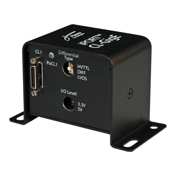
Chapter 3 CL-GigE Connections This chapter describes the CL-GigE connections, including connector details and pinout information. When the CL-GigE is powered, you can observe the status LEDs. The following topics are covered in this chapter: • “Connector and Switch Locations” on page 12 •... -
Page 22: Connector And Switch Locations
I/O Level switch 2-position DIP switch Selects the voltage for single-ended GPIO inputs and outputs (3.3 V or 5 V). For more information, see “Differential Type and I/O Level Switches” on page 19. iPORT CL-GigE External Frame Grabber User Guide... -
Page 23: Rj-45 Locking Connectors
RJ-45 Locking Connectors The CL-GigE supports the Type 090 RJ-45 locking connectors specified by the GigE Vision Standard, Mechanical Supplement, version 1.0 draft A. The enclosure includes threaded screw holes that comply with the connectors specified in the standard. Threaded screw holes Camera Link Connector The CL-GigE supports one Base Camera Link camera, which streams image data to the CL-GigE. -
Page 24: Powering A Camera Using Power Over Camera Link (Pocl)
For information about viewing the SafePower status and the status changes that occur, including PoCL Sensing, see “Enabling SafePower and PoCL” on page 58. Mapping to the Serial Communication Interface The CL1 Camera Link connector is mapped to the Bulk0 serial communication interface on the CL-GigE. iPORT CL-GigE External Frame Grabber User Guide... -
Page 25: Mapping Of Camera Link Connector And 12-Pin Gpio Connector Inputs
Mapping of Camera Link Connector and 12-Pin GPIO Connector Inputs The GPIO pins on the 12-pin GPIO connector allow an external signal to control a Camera Link camera, and are typically used for triggering. For example, you can use a trigger to synchronize image capture from multiple cameras or to synchronize image capture with an external device. -
Page 26: 12-Pin Gpio Connector
Differential input0 negative GpioIn0 Do not connect for single-ended operation. Pin 10 provides the single-ended connection. GPIO_OUT0 Single-ended output GpioOut0 GPIO_IN0+ Differential input0 positive GpioIn0 Can be used as a single-ended input (optional). iPORT CL-GigE External Frame Grabber User Guide... -
Page 27: Mounting The 12-Pin Gpio Connector To An Enclosure Backplate
Table 6: 12-Pin GPIO Connector Pinouts (Continued) Function Type PLC signal Notes GPIO_IN3 Single-ended input GpioIn3 GPIO_IN2 Single-ended input GpioIn2 Mounting the 12-Pin GPIO Connector to an Enclosure Backplate The CL-GigE is optionally available with a removable 12-pin GPIO connector and the corresponding GPIO board that are suitable for mounting to a client-sourced enclosure. - Page 28 9 and pin 1 on the 12-pin connector are inserted through Line up tab between the bottom two pinholes the two bottom pins Tab location GPIO board and 12-pin male connector (assembled) iPORT CL-GigE External Frame Grabber User Guide...
-
Page 29: Differential Type And I/O Level Switches
Differential Type and I/O Level Switches The Differential Type and I/O Level switches are used to configure the CL-GigE to work with single- ended and differential inputs. Differential Type switch Differential Type switch I/O Level switch I/O Level switch OEM board set In mountable enclosure Warning: To avoid damage to the CL-GigE and connected equipment (or reduced lifetime of the Differential Type... - Page 30 Set the I/O Level switch Input/output type switch to... to... Single-ended inputs and LVCMOS DIFF 3.3 V outputs DIFF HVTTL/HVCMOS/HTL HVTTL Differential inputs LVDS LVDS RS-422 LVDS or DIFF +/-24 V or +/-30 V DIFF iPORT CL-GigE External Frame Grabber User Guide...
-
Page 31: Differential And Single-Ended Input/Output Specifications
Differential and Single-Ended Input/Output Specifications The input and output specifications vary, depending on how the Differential Type and I/O Level switches are set, as listed in the following tables. Warning: To avoid damage to the CL-GigE and connected equipment (or reduced lifetime of the Differential Type switch), ensure you observe the following precautions: •... - Page 32 Low maximum 0.55 V (@24 mA) 0.55 V (@ 32 mA) Maximum delay 6.4 nsec ESD protection Up to class -4 (+/-15 kV) EMI filtering Serial ferrite bead 120 Ohm @ 100 MHz iPORT CL-GigE External Frame Grabber User Guide...
-
Page 33: Powering The Cl-Gige
Powering the CL-GigE The CL-GigE can be powered using Power over Ethernet (PoE) which uses isolated PoE circuitry or through an external power supply. Powering the CL-GigE Using PoE One of the ways that you can power the CL-GigE is with PoE. When you power the CL-GigE this way, the PoE power source can be either a PoE power injector or a PoE-enabled GigE switch. -
Page 34: Powering The Cl-Gige Using An External Power Supply
Tip: We recommend that you connect the CL-GigE to your computer’s NIC or a GigE switch before you apply power. Supply 12 V power to the 12-pin GPIO connector on the CL-GigE. iPORT CL-GigE External Frame Grabber User Guide... -
Page 35: Power Consumption
Apply power to the camera: • If you plan on powering the camera using PoCL, use eBUS Player to enable PoCL (using the ClSafePowerActive feature). For more information, see “Enabling SafePower and PoCL” page 58. • If you are not powering the camera using PoCL, connect the camera to a power supply. If you are not using PoCL, the camera’s ground must be electrically floating or attached to the 12 V external power supply ground. -
Page 36: Status Leds
Off: No connection, 10 Mbps connection, or 100 Mbps connection. connection speed Green: 1 Gbps connection. PoCL1 Green: Power over Camera Link (PoCL) is active and the camera is being powered using PoCL. Off: The camera is not receiving power through PoCL. iPORT CL-GigE External Frame Grabber User Guide... -
Page 37: Ambient And Junction Temperatures
Chapter 4 Ambient and Junction Temperatures This chapter provides you with the information you need to ensure the optimal operating temperature for your CL-GigE OEM board set. You should store the CL-GigE at temperatures between -40°C to +85°C. This chapter lists the components that consume the largest amount of power on the CL-GigE OEM board set, and will therefore be most affected by high temperatures. - Page 38 • ~ 980 mW Θ JC = (Tj - Ta)/Ptop, where Ptop = Power dissipation from the top of the package. Θ JA = (Tc - Ta)/P, where P = Total power dissipation. iPORT CL-GigE External Frame Grabber User Guide...
-
Page 39: Handling Gpio, Camera Control, And Plc Input And Output Programming Signals
Chapter 5 Handling GPIO, Camera Control, and PLC Input and Output Programming Signals The CL-GigE includes a programmable logic controller (PLC) that lets you control external machines and react to inputs. By controlling your system using the PLC, you can make functional changes, adjust timing, or add features without having to add new hardware. -
Page 40: Plc Input And Output Programming Signals
No associated pin PlcLval0 In, out No associated pin PlcMval0 In, out No associated pin PlcTrig0 In, out No associated pin PlcTimestampCtrl In, out No associated pin Timer0Trig In, out No associated pin iPORT CL-GigE External Frame Grabber User Guide... - Page 41 Table 16: PLC Signal Usage (Continued) Associated pin on the 12-pin Signal name PLC equation usage Camera Link connector GPIO connector Timer0Out No associated pin Timer1Trig In, out No associated pin Timer1Out No associated pin Timer2Trig* In, out No associated pin Timer2Out* No associated pin Timer3Trig*...
-
Page 42: Using Quadrature Encoders
This change is also used for detecting speed of motion. When these signals are steady-state, and are not producing square wave signals, the motion has stopped. For information about the electrical interface on the CL-GigE, see “Differential Type and I/O Level Switches” on page 19. iPORT CL-GigE External Frame Grabber User Guide... -
Page 43: Differential Connection
Differential Connection The following diagram illustrates a typical differential connection to a quadrature encoder. Figure 2: Typical Differential Connection to Quadrature Encoder Single-Ended Connection The following diagram illustrates a typical single-ended connection to a quadrature encoder. Figure 3: Typical Single-Ended Differential Connection to Quadrature Encoder Industrial Models Quadrature Encoder Single‐Ended Outputs... -
Page 44: Processing Quadrature Encoder Signals
When the conveyor belt moves in the reverse direction, signal A lags signal B by 90°. The PLC provides a trigger signal on the Camera Link control line Pb0CC0 only when signal A leads signal B by 90°. iPORT CL-GigE External Frame Grabber User Guide... - Page 45 The Timer0 function in the PLC is used to generate the trigger pulse Timer0Out. Timer0 itself is triggered by the falling edge of a Boolean combination of A and B signals, which obtains the correct quadrature phase for the forward direction. Another Boolean combination is used to produce the trigger signal Pb0CC0 from signal B and Timer0Out;...
-
Page 47: Bulk Interfaces
Chapter 6 Bulk Interfaces The CL-GigE has one UART interface for serial communication with a connected Camera Link camera. The following topics are covered in this chapter: • “GenICam Interface for Serial Communication Configuration” on page 38 • “UART Timing” on page 38 Bulk Interfaces... -
Page 48: Genicam Interface For Serial Communication Configuration
Predefined rates: 9600, 14 400, 19 200, 28 800, 38 400, 57 600, 115 200, 230400*, 460800*, and 921,600* • Programmable • Loop back mode from downstream to upstream *Available in release 1.3.1 (and later) of the CL-GigE firmware. Figure 4: UART Timing iPORT CL-GigE External Frame Grabber User Guide... - Page 49 A number of preset baud rates can be used. If you require a baud rate that is not covered by the presets, you can specify your own baud rate. To specify your own baud rate: In the Device Control dialog box, under Port Communication, choose Programmable in the BulkBaudRate list.
-
Page 51: Installing The Ebus Sdk
• “Installing the eBUS Universal Pro Driver” on page 42 Installing the eBUS SDK You can install the Pleora Technologies eBUS SDK on your computer to configure and control your CL-GigE. The eBUS SDK includes: • Pleora’s eBUS Player application, which allows you to control the CL-GigE parameters and view video from a video source connected to the CL-GigE. -
Page 52: Installing The Ebus Universal Pro Driver
After a moment the driver status changes. If you are installing a driver, the driver is installed across all network adapters on your computer. Close the eBUS Driver Installation Tool. You may be required to restart your computer. To see the versions of the installed drivers, click Help > About. iPORT CL-GigE External Frame Grabber User Guide... -
Page 53: Configuring Your Computer's Nic For Use With The Cl-Gige
Chapter 8 Configuring Your Computer’s NIC for use with the CL-GigE When using the CL-GigE and connected Camera Link camera, you may observe high data rates (above 800 Mb/s) that are close to the physical limit of Gigabit Ethernet (1000 Mb/s). This chapter provides guidance on how to configure your CL-GigE to maximize the performance of your system. -
Page 54: Configuring The Nic For Communication With The Cl-Gige
The instructions in this section are based on the Windows 10 operating system. The steps may vary depending on your computer’s operating system. To configure the NIC for optimal performance In the Windows Control Panel, click Network and Internet. Click Network and Sharing Center. iPORT CL-GigE External Frame Grabber User Guide... - Page 55 In the left-hand panel, click Change adapter settings. Configure the NIC for jumbo packets (more often referred to as jumbo frames) and set the NIC’s Receive Buffers (Receive Descriptors) to the maximum available value. Using jumbo packets allows you to increase system performance. However, you must ensure your NIC and GigE switch (if applicable) support jumbo packets.
-
Page 56: Calculating The Required Bandwidth
The Width, Height, and PixelSize have a direct effect on the bandwidth that is used between the CL-GigE and the computer. Increasing the width and the height of the image will result in larger frames being streamed from the CL-GigE. iPORT CL-GigE External Frame Grabber User Guide... -
Page 57: Acquisition Frame To Skip
Acquisition Frame to Skip If the CL-GigE drops frames because of high bandwidth usage (close to 1 gigabit), you can reduce the bandwidth by adjusting the AcquisitionControl\AcquisitionFrameToSkip feature. You can set this feature to 2 to skip two frames and then send one frame, resulting in one out of every three frames being sent, for example. -
Page 59: Connecting To The Cl-Gige And Configuring General Settings Using Ebus Player
Chapter 9 Connecting to the CL-GigE and Configuring General Settings Using eBUS Player After you have set up the physical connections to the CL-GigE, you can start eBUS Player to configure image settings, which will help ensure that images are received and displayed properly. You can also configure the buffer options to reduce the likelihood of lost packets. -
Page 60: Confirming Image Streaming
* The ClSafePowerActive feature enables the SafePower protocol on the CL-GigE so it can supply power using PoCL. This protocol also prevents the CL-GigE from attempting to supply power to a camera that does not support PoCL. Click OK. eBUS Player is now connected to the CL-GigE. iPORT CL-GigE External Frame Grabber User Guide... - Page 61 To turn the test pattern on or off Start eBUS Player and connect to the CL-GigE. For more information, see “To start eBUS Player and connect to the CL-GigE” on page 50. Under Parameters and Controls, click Device control. Under ImageFormatControl, click a test pattern option in the TestPattern list. Close the Device Control dialog box.
-
Page 62: Providing The Cl-Gige With An Ip Address
To configure a persistent IP address Start eBUS Player and connect to the CL-GigE. For more information, see “To start eBUS Player and connect to the CL-GigE” on page 50. Under Parameters and Controls, click Device control. iPORT CL-GigE External Frame Grabber User Guide... - Page 63 Under TransportLayerControl\GigEVision, set the GevCurrentIPConfigurationPersistentIP feature to True. Set the GevPersistentIPAddress feature to an IP address that is compatible with your computer’s NIC. Set the GevPersistentSubnetMask feature to a compatible subnet mask address. Optionally, enter a compatible default gateway in the GevPersistentDefaultGateway field. Close the Device Control dialog box.
-
Page 64: Accessing Your Camera Settings Through Camera Link Serial Communications
Tip: If you need to set the parity and stop bits, click Device control on the main page of eBUS Player. In the Visibility list, click Guru. Under IP Engine > PortCommunication, set the values for these options. iPORT CL-GigE External Frame Grabber User Guide... -
Page 65: Configuring Cl-Gige Image Settings Using Ebus Player
Under Send as, select the data transmission sequence format by clicking either ASCII (text only) or Hexadecimal. Type the data string in the Data box. For hexadecimal, enter a pair of hexadecimal digits for each byte, separated by spaces. For example, 01 23 45 67 89 AB CD EF. - Page 66 50. In the Visibility list, click Expert. Under DeviceControl, select a sensor scan type (areascan or linescan) in the DeviceScanType list. Under ImageFormatControl, select the number of taps in the SensorDigitizationTaps list. iPORT CL-GigE External Frame Grabber User Guide...
- Page 67 DeviceScanType, SensorDigitizationTaps, PixelFormat, and TestPattern are interrelated. When you change any of these values, the CL-GigE may automatically adjust the other values to ensure the configuration is valid. Under ImageFormatControl, enter the image width and height, and select a pixel format from the PixelFormat list.
-
Page 68: Enabling Safepower And Pocl
“To start eBUS Player and connect to the CL-GigE” on page 50. In the Visibility list, click Expert or Guru. Under CameraLinkInterfaceControl, select Connector1 in the ClConnectorSelector list. In the ClSafePowerActive list, click True to enable SafePower and PoCL. iPORT CL-GigE External Frame Grabber User Guide... - Page 69 Review the status that appears under ClSafePowerStatus. The following flowchart explains the status changes. Initializing. The detection of a PoCL camera and cable has not started yet. PoClSensing. The CL-GigE is determining if a PoCL camera and cable are connected. What type of camera/cable is detected? Non-PoCL...
-
Page 70: Viewing And Testing Streaming Images
Example image. When the test pattern is enabled for the CL-GigE, a stream of moving lines will appear (often black, gray, and white) instead of video from your camera. If images or the test pattern do not stream, see the tips provided in “System Troubleshooting” on page 83. iPORT CL-GigE External Frame Grabber User Guide... -
Page 71: Configuring The Buffers
Configuring the Buffers You can increase the buffer count using eBUS Player to make streaming more robust. A high number of buffers are needed in high frame rate applications, while a small number of buffers are needed for lower frame rates. Latency increases as the number of buffers increases. To configure the buffers Start eBUS Player. -
Page 72: Specifying How Images Are Acquired
Acquisition starts when the Play button is pressed (the AcquisitionStart command is executed). Device Control Dialog Box eBUS Player Main Page Continuous Mode This mode allows you to acquire images continuously and is the default mode for most external frame grabbers. iPORT CL-GigE External Frame Grabber User Guide... -
Page 73: Mulitframe Mode
Mulitframe Mode This mode allows you to acquire a fixed number of images. To configure the number of images, set the CL-GigE’s AcquisitionControl > AcquisitionFrameCount feature. You can set the AcquisitionControl > AcquisitionFrameCount feature in the Device Control dialog box, as shown in the following image. -
Page 74: Recording And Retrieving Images In The Onboard Memory
“Understanding When Images are Removed from the Onboard Memory” on page 66. To determine how many images can be stored in memory, see “Calculating How Many Images Can be Stored in Onboard Memory” on page 66. iPORT CL-GigE External Frame Grabber User Guide... -
Page 75: Continuousreadout Mode
ContinuousReadout Mode With this mode, images are continuously read (and removed) from the CL-GigE’s onboard memory. The readout begins at the first image in memory. To see the number of images stored in onboard memory, see AcquisitionControl > BlockBufferCount in the Device Control dialog box (Expert or Guru visibility level is required). -
Page 76: Understanding When Images Are Removed From The Onboard Memory
Pleora Support Center at supportcenter.pleora.com. • eBUS SDK API Help Files, which are installed on your computer during the installation of the eBUS SDK. You can access this documentation from the Windows Start menu under eBUS SDK. iPORT CL-GigE External Frame Grabber User Guide... -
Page 77: Saving Ebus Player And Cl-Gige Settings
Chapter 10 Saving eBUS Player and CL-GigE Settings This chapter describes the various ways to save your eBUS Player and CL-GigE settings. The changes that you make to your CL-GigE are temporary and WILL NOT PERSIST ACROSS POWER CYCLES unless you save the changes to the flash memory of the CL-GigE or to a .pvcfg file on your computer. The following topics are covered in this chapter: •... -
Page 78: Choosing The Best Method For Saving Ebus Player And Cl-Gige Settings
Player). Image stream parameters. These parameters are set using the Image Stream Control dialog box (click the Image stream control button on the main page of eBUS Player). iPORT CL-GigE External Frame Grabber User Guide... - Page 79 Table 24: eBUS Player and CL-GigE Settings Saving Options (Continued) Format and location of saved settings: Saves to a .pvcfg file on Saves to your Saves to the CL-GigE your computer computer’s user profile flash memory eBUS Player procedure for saving: Tools >...
-
Page 80: Using File > Save
Player settings saved using this method, see “eBUS Player and CL-GigE Settings Saving Options” on page 68. The Device control settings and the Image stream control settings are not saved when you click Save Preferences. iPORT CL-GigE External Frame Grabber User Guide... -
Page 81: Using User Sets: Saving Settings To The Cl-Gige's Flash Memory
To save eBUS Player preferences • Click Tools > Save Preferences. The eBUS Player preferences, including the Communication control options such as a specific heartbeat interval and answer timeout value, are saved. To restore default eBUS Player settings • Click Tools > Restore Default Preferences. Settings are restored to the values set on the CL-GigE before it was first used. -
Page 82: Ensuring Configuration Settings Are Not Overwritten
This allows you to view the CL-GigE’s GenICam XML file; it does not save your eBUS Player or camera settings. To save your camera’s XML file Click Tools > Save GenICam XML. Navigate to the location in which you want to save the XML file. Click Save. iPORT CL-GigE External Frame Grabber User Guide... -
Page 83: Network Configurations For The Cl-Gige
Chapter 11 Network Configurations for the CL-GigE After you have connected to the CL-GigE and provided it with a unique IP address on your network, you can configure the CL-GigE for either unicast or multicast. The following topics are covered in this chapter: •... -
Page 84: Unicast Network Configuration
Power supply or, if using PoE, a PoE power injector or PoE-enabled GigE switch • GigE switch (optional) • CAT5e or CAT6 Ethernet cables • Desktop computer or laptop with eBUS SDK installed iPORT CL-GigE External Frame Grabber User Guide... -
Page 85: Cl-Gige Configuration - Unicast Network Configuration
CL-GigE Configuration — Unicast Network Configuration After you have connected and applied power to the hardware components, use eBUS Player to configure the CL-GigE. To configure the CL-GigE for a unicast network configuration Start eBUS Player. Click Tools > Setup. Under eBUS Player Role, click Controller and data receiver. -
Page 86: Multicast Network Configuration
Compatible display monitor • Cable to connect the vDisplay HDI-Pro External Frame Grabber to the display monitor • GigE switch • CAT5e or CAT6 Ethernet cables • Desktop computer or laptop with eBUS SDK installed iPORT CL-GigE External Frame Grabber User Guide... -
Page 87: Configuring The Devices For A Multicast Network Configuration
Connecting the Hardware and Power The following procedure explains how to connect the power, network, and data cables to the vDisplay HDI-Pro External Frame Grabber and CL-GigE. To connect the network cables and apply power Connect one end of a CAT5e/CAT6 cable to the Ethernet connector on your computer’s NIC. Attach the other end to an available port on the GigE switch. - Page 88 Set GevSCDA to a multicast address (for example, 239.192.1.1). Close the Device Control dialog box. Now, configure the CL-GigE, as outlined in “To configure the CL-GigE for a multicast network configuration” on page 79. iPORT CL-GigE External Frame Grabber User Guide...
- Page 89 To configure the CL-GigE for a multicast network configuration Start an additional instance of eBUS Player. Click Tools > Setup. Under eBUS Player Role, click Controller and data receiver, as shown in the following image. Under GigE Vision Stream Destination, click Multicast and enter the IP address and port number. The address and port must be identical to that configured for the vDisplay HDI-Pro External Frame Grabber in step 8 and 9 of “To configure the vDisplay HDI-Pro External Frame Grabber for a...
- Page 90 Under TransportLayerControl > GigEVision, ensure that the port in the GevSCPHostPort field and the multicast IP address in the GevSCDA field are correct. They are configured automatically to the values set in step 4 of this procedure. Close the Device Control dialog box. iPORT CL-GigE External Frame Grabber User Guide...
- Page 91 Click Play to view the source image stream both on the computer and the display monitor. Example image. When the test pattern is enabled for the CL-GigE, a stream of moving lines will appear (often black, gray, and white) instead of video from your camera. Network Configurations for the CL-GigE...
-
Page 93: System Troubleshooting
CL-GigE. It also shows you how to switch between the backup and main firmware loads. Not all scenarios and solutions are listed here. You can refer to the Pleora Technologies Support Center at supportcenter.pleora.com for additional support and assistance. - Page 94 You can view the CL- GigE IP address information in the Available Devices list in eBUS Player. A red icon appears beside the device if there is an incompatible IP configuration. iPORT CL-GigE External Frame Grabber User Guide...
- Page 95 Table 26: Troubleshooting Tips (Continued) Symptom Possible cause Resolution SDK is able to connect, but In a multicast configuration, Images might not appear on the display if you no images appear in eBUS the CL-GigE may not be have not configured the CL-GigE for a multicast Player.
- Page 96 Black bars appear on the Camera does not output In eBUS Player, adjust the Width, Height, and sides of the images images using the full image image offset features until the black bars no size longer appear. iPORT CL-GigE External Frame Grabber User Guide...
-
Page 97: Changing To The Backup Firmware Load
Changing to the Backup Firmware Load In the event that the main firmware load fails to start, the CL-GigE will start up using the backup firmware load when it is restarted or power cycled. In the rare event that the backup load is not used automatically (as indicated by the fact that eBUS Player will not be able to detect the CL-GigE), you can use the slide switch to change to the backup load. -
Page 99: Reference: Mechanical Drawings And Material List
Reference: Mechanical Drawings and Material List This chapter provides mechanical drawings and also provides a list of connectors with corresponding manufacturer details. Three-dimensional (3-D) mechanical models are available at the Pleora Technologies Support Center. The following topics are covered in this chapter: •... -
Page 100: Mechanical Drawings
Connectors are dimensioned to the center. Enclosed Model Figure 7: Enclosed Model — Camera Link Connector View 59.10 31.70 6.70 21.25 61.25 Figure 8: Enclosed Model — Side View 54.56 47.60 iPORT CL-GigE External Frame Grabber User Guide... - Page 101 Figure 9: Enclosed Model — GPIO Connector View 40.05 51.00 38.83 1.30 21.50 50.25 Figure 10: Enclosed Model — Bottom View 29.97 7.00 71.50 82.50 12.70 4.76 Reference: Mechanical Drawings and Material List...
-
Page 102: Cl-Gige Oem Board Set With 12-Pin Gpio Connector
Figure 11: OEM Board Set with GPIO: Maximum Component Height MAX COMPT HEIGHT=2.10 HT=11.46 SECONDARY SIDE Figure 12: OEM Board Set with GPIO: Component Height Adapter Board Adapter Board HT=3.50 HT=4.87 HT = 1.00 2 PLACES HT=3.45 iPORT CL-GigE External Frame Grabber User Guide... - Page 103 Figure 13: OEM with GPIO: Adapter Board Detailed Measurements 2.70 2 PLACES 32.50 30.00 28.00 24.00 17.51 17.00 9.49 4.00 0.00 2.00 4.50 Figure 14: OEM Board Set with GPIO: GigE PHY Board Detailed Measurements 32.50 30.30 31.30 28.00 27.83 16.71 17.17 15.04...
- Page 104 Figure 15: OEM Board Set with GPIO: Maximum Component Height 54.86 8.00 42.17 1.95 15.88 COMPT HEIGHT 1.60 5.50 1.60 15.97 1.60 8.00 NOTE: JACK SOCKETS WILL BE FASTENED TO CUSTOMER PANEL. PANEL THICKNESS WILL ADD TO THIS DIMENSION. iPORT CL-GigE External Frame Grabber User Guide...
-
Page 105: Cl-Gige Oem Board Set With No 12-Pin Gpio Connector
CL-GigE OEM Board Set with no 12-Pin GPIO Connector The drawings in this section show the CL-GigEB-IND OEM board set (order code 900-6009) without the 12-pin GPIO connector soldered to the board. Figure 16: OEM Board Set No GPIO Connector: Maximum Component Height MAX COMPT HEIGHT=2.10 HT=11.46... - Page 106 24.00 17.51 17.00 9.49 4.00 0.00 2.00 4.50 Figure 19: OEM Board Set No GPIO Connector: GigE PHY Board Detailed Measurements 30.30 32.50 29.95 28.00 16.71 15.45 15.04 11.50 6.90 1.96 0.00 4.50 iPORT CL-GigE External Frame Grabber User Guide...
- Page 107 Figure 20: OEM Board Set No GPIO Connector: Maximum Component Height 48.47 8.00 2.10 42.17 15.88 COMPT HEIGHT 1.60 5.50 1.60 1.60 8.00 NOTE: JACK SOCKETS WILL BE FASTENED TO CUSTOMER PANEL. PANEL THICKNESS WILL ADD TO THIS DIMENSION. HT=2.80 Reference: Mechanical Drawings and Material List...
-
Page 108: Gpio Board Assembly
The drawings in this section show the GPIO board assembly that is included with the CL-GigEB-IND Development Kit (the development kit order code is 900-6011). Figure 21: GPIO Board — Front and Back Views Figure 22: GPIO Board — Dimensions iPORT CL-GigE External Frame Grabber User Guide... - Page 109 Figure 23: GPIO Board — Dimensions (Continued) Figure 24: GPIO Board — Side Views Reference: Mechanical Drawings and Material List...
-
Page 110: Material List
Table 27: Connector Summary Description Manufacturer part number Manufacturer RJ-45 connector RJHSE-3P85 Amphenol 12-pin circular connector HR10A-10R-12PB(71) Hirose Electric Co. Ltd. Miniature Camera Link 12226-1100-00FR Source manufacturer, description, and identification may vary for each connector. iPORT CL-GigE External Frame Grabber User Guide... -
Page 111: Appendix: Timing For Camera Link Signals
Chapter 14 Appendix: Timing for Camera Link Signals The output of the camera must match the format of the CL-GigE. You should select a case for your application and then refer to “Timing Values for All Cases” on page 103. The stated timing restrictions are minimum values. -
Page 112: Case 2: Fval And Lval Are Edge-Sensitive
(the next FVAL edge occurs before all of the lines have been acquired). FV2FV FI2FV FV2DV FV2FI LV2LI PB_FVAL PB_LVAL FV2LV LI2LV PB_DVAL (N-1, (N-1, PB_DATAx] (0,0) (1,0) (N,0) (0,1) (1,1) (N,M) (0,0) (1,0) LV2DV Don’t Care Window Size = N x M iPORT CL-GigE External Frame Grabber User Guide... -
Page 113: Case 3: Fval Is Edge-Sensitive And Lval Is Level-Sensitive
Case 3: FVAL is Edge-Sensitive and LVAL is Level-Sensitive In this case, FVAL is edge-sensitive and LVAL is level-sensitive. • Start of frame/line is signaled by: A rising (or falling) edge on FVAL, which signals start of frame. The line is valid when LVAL is active (high or low depending on settings). •... - Page 114 The valid state of DVAL is high when it is set as level-high sensitive, and low when set as level-low sensitive. DVAL is always valid in the grabber when the parameter PixelBusDataValidEnabled is off. If FVAL becomes invalid and LVAL is still valid, the line is truncated. iPORT CL-GigE External Frame Grabber User Guide...
-
Page 115: Reference: Mean Time Between Failures (Mtbf) Data
Chapter 15 Reference: Mean Time Between Failures (MTBF) Data The following table provides MTBF data. Table 29: MTBF Data Model MTBF @ 40°C CL-GigE External Frame Grabber 1,014,151 hours Assumptions: The calculation is performed using the RelCalc for Windows V5.1-TELC3 software, which implements Telcordia SR-332 (Issue 3) failure rate models. -
Page 117: Technical Support
Chapter 16 Technical Support On the Pleora Support Center, you can: • Download the latest software and firmware. • Log a support issue. • View documentation for current and past releases. • Browse for solutions to problems other customers have encountered. •...
Need help?
Do you have a question about the iPORT CL-GigE and is the answer not in the manual?
Questions and answers